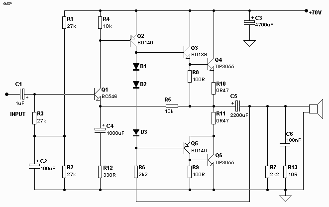
Figure 1 - My Remembered
(and Slightly Modified) Version of the El-Cheapo

| Elliott Sound Products | Project 12 |
"Semi-Original Design" - What is that supposed to mean? Well, many years ago, there was an amplifier circuit in a magazine (I don't remember which one, but I think it was a US edition). This amp was called "El-Cheapo", and used a single power supply and capacitor coupled speaker. I do not recall the exact circuit details well, but it was a very simple amp, and used quasi-complementary symmetry for the output stage. Note the really sneaky way the Class-A driver amp's collector load is bootstrapped !
For those younger than I who have no idea what I'm talking about, quasi-complementary symmetry was a scheme used in the days when PNP power transistors were expensive and useless. If you wanted any sort of voltage and current rating, you had to use NPN devices. The quasi-complementary output stage used a (discrete) darlington for the positive side, and a complementary pair for the negative (i.e. a PNP driver coupled to an NPN power transistor).
Figure 1 shows the circuit as I remember it (with component values re-calculated - I have no idea what they used to be, but those shown should be pretty close), and it was a cheap amp compared to most offerings of the day. It also managed to sound respectable - again by comparison - and I and many of my friends of the day built these amps with abandon - guitar amps, hi-fi, you name it, El-Cheapo was in there!
Note that the transistor types are "modern" equivalents - I cannot remember what the originals were, but they are almost certainly obsolete. It is also likely upon reflection that R6 was probably closer to 4k7, since the speaker provides the DC voltage return for the bootstrap circuit, and is only 6 Ohms or so DC resistance.
Another change is the speaker coupling capacitor - I do remember that it was 1000uF (for a -3dB of 20Hz and a 8 Ohm load). This is too small, and the 2200uF shown is actually marginal. 4700uF would be better, or even more - but that would defeat the purpose, since the amp would no longer be cheap. Besides that, it still has a single supply, and such amps are not well considered by anyone these days.
Figure 1 - My Remembered
(and Slightly Modified) Version of the El-Cheapo
These were the days when the 2N3055 was the pre-eminent power transistor (NPN of course), and there were no vaguely equivalent PNP devices for less than about 5 times the price, and even these were highly inferior. As a result, the quasi-complementary output was very common, until decent PNP power devices became more readily available. Immediately, just about everyone started using NPN and PNP darlington coupled devices for the output stages (as shown for Q3 and Q4) - the funny part is that it was demonstrated back in the mid 1970's that the full darlington connection actually sounds worse than quasi-complementary stages. Is not progress a wonderful thing?
It was with some (a lot, actually) surprise that many years later I saw the circuit diagram for a well known (and highly respected) British hi-fi amp, and it was virtually identical to the original El-Cheapo - this was well after everyone else - including me - was designing amps with a long-tailed pair for the input stage.
So, I got to thinking about this (as I have done many times, but it never went anywhere), since the input stage of the El-Cheapo is not subject to the phase problems of the long tailed pair, and amps with this input stage tend to be inherently stable. They do have a problem with DC offset (which was not a problem with capacitor coupled speakers), but this can be solved with a DC servo circuit using an opamp, or a simple bias offset can be used.
As shown, the gain for audio frequencies is 31 (30dB), which means an input sensitivity of 700mV for an output of 60W (near enough to 0dBm). This remains unchanged for the variations following.
Figure 2 shows the circuit of the amp in basic form, remaining fairly true to the original concept except for the dual power supply, direct-coupled speaker and a bias servo allowing lower value emitter resistors for the output stage. A DC offset control is mandatory here, and the LED is used as a stable voltage reference for the offset voltage. With a solid power supply (such as that described for the 60W Power Amp), this amp is perfectly capable of 60 to 70W into 8 Ohms. Additional output transistors can be connected in parallel to allow for 4 Ohm loads, where 100W should be readily achieved.
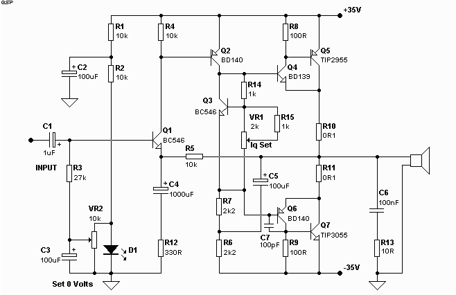
Figure 2 - The "New Improved"
El-Cheapo
The Class-A driver is perfectly normal, but can be improved by using a bootstrapped buffer transistor, and the use of a current sink load for the Class-A driver will improve gain and linearity. As shown, the Class-A driver load is still a bootstrap circuit. With a sufficiently large capacitor to allow for the lowest frequencies, good linearity is obtained, with the driver current remaining effectively constant for the full swing of the amp.
Even without the buffer on the Class-A amp stage, a simulation (admittedly using "ideal" transistors) of the input and Class-A stage shows a gain of about 100dB, or 100,000 with a current sink of 100k Ohms. This is approximately what can be expected from the bootstrap circuit due to the losses in the output stage.
A useful increase in gain may be achieved by increasing the current through Q1, by reducing the value of R4. There is a problem with this however, since the voltage across R5 becomes excessive, raising the input DC voltage on the base of Q1. One can reduce the value of R5 (the feedback resistor) but then the required capacitance of C4 becomes too high to be sensible because R12 must be reduced for the same audio gain.
The input capacitor has been changed to a polyester (or similar) and with 1uF has a lower -3dB frequency of 7Hz. This may be made larger if your speakers can go lower than that. One thing you cannot do with this input stage is direct couple from a preamp. The voltage on the base of Q1 will be about 1.3V for 0 Volts at the speaker output. If the input were grounded, then there will be -1.3V across the speakers - this is generally considered to be a bad idea. It is only 200mW for an 8 Ohm load, but it should be avoided.
Speaking of feedback - because the input stage creates an inherently stable amp, there is no reason to expect that TIM (Transient Intermodulation Distortion) will be a problem, since feedback is simply applied to the emitter of the input amp, and little or no frequency "compensation" is needed. This is an area where some experimentation is needed, and it might be necessary to connect a low value (47pF ?) capacitor between collector and base of Q2 - it was not needed in the original, but this configuration has vastly more gain.
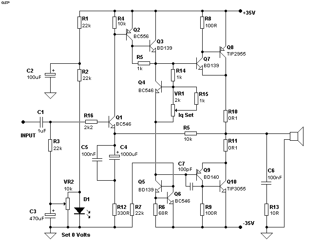
Figure 3 - The "Even-Newer
More-Improved" El-Cheapo
I tend to like Figure 2, since it appeals to my KIS approach (Keep It Simple) towards all things electronic, while still maintaining a sensible attitide towards providing adequate feedback and other techniques to minimise distortion. Having said that, Figure 3 is probably going to be the better amp overall, since it will have better linearity before feedback is applied.
The astute reader will realise by now that the entire Class-A driver and output circuits are virtually identical to many of the high-end amp designs one can find on the Web and in magazines (etc). The only bit missing is the long tailed pair input stage, and its current source in the tail, and the current mirrors in the collector circuits. Oh, and the mandatory "Miller" capacitor to limit frequency response for stability and all the other stuff one finds in input circuits.
In so many cases. it seems that the amp circuits one sees have been designed for the sole reason to use more components than any other on the planet, and the next one you see is even worse.
Construction of any of these variations is non-critical, within the normal bounds of amplifier building at least, and will not be discussed in any detail. I will, however, make the following observations.
I would recommend that Figure 1 be avoided. Use of an electrolytic capacitor in the speaker output is not a good thing, and measurements made by Doug Self (and others) show low frequency distortion is generated by electros (although the actual mechanism that creates the distortion is unclear).
Naturally, this circuit (absolutely) cannot be DC coupled - but I know for a fact that I cannot hear DC, my speakers will not reproduce it, DC will not be recorded and no musical instrument creates it - so why should I (or anyone else) bother?
The bias servo (Fig 2, Q3 or Fig 3, Q4) is designed to allow enough adjustment of the voltage between the bases of the driver transistors to allow accurate bias setting - this transistor should not be mounted on the heatsink, unless the drivers are also mounted there (which I do not recommend!). Quiescent (no-load) current should be about 100mA, measured across the 0.1 Ohm emitter resistors - this will give a reading of 10mV on a multimeter.
The trimpot VR2 is used to set the DC voltage at the output to 0 Volts (+/- 50mV). This should be set finally after the amp has had time to stabilise, which will require at least 30 minutes of operation.
Make sure that there is sufficient heatsinking for the power transistors to avoid excessive temperature rise. I tend to prefer a heatsink which is too large rather than the other way 'round, and anything better than about 1 degree C / Watt should be good - if a little on the large and expensive side. This will be the same for any amplifier you build, regardless of complexity for a given output power.
With this amp (or any amp of similar power) quiescent power is less than 10W (based on a current of 100mA, and given that the power supply voltage will be higher than the nominal 35V), and at worst case dissipation will reach a maximum of about 75 Watts. It is uncommon - but possible - for amps to run at their worst case dissipation during normal use, but it should be accounted for. With a heatsink of 1oC/W, this means that the transistors may reach a temperature of 100oC or more, which will reduce their life expectancy considerably. With heatsinks, size does matter.
Further, I am yet to be convinced that a power amp with dual (or even triple) long tailed pairs, cascode mirror image Class-A drivers, abundant (rampant?) current mirrors, fully DC coupled and 37 compensation and bypass capacitors scattered throughout the circuit sound any better than the amp described in Project 03 in my project pages. I might be wrong (it happened once), but I do believe that a good simple design is just as capable, and may even sound better than one which has been over-designed to such an extent as to be (to me, anyway) completely over the top.
If it doesn't (sound better, that is), then one must ask if the improvement is worth all the extra effort (and cost). There has to be a limit somewhere, and many of us cannot justify 20 output transistors each in 4 monoblock 100W Class-A systems (bi-amped, naturally) when the speakers, room acoustics and recording techniques (plus the demands or restrictions imposed by s/he who must be obeyed) simply do not come even close to the standard of a passably decent power amplifier. Besides, who wants a 2kW heater in the listening room in the middle of summer anyway.
The point of all of this is that I do not believe that the perceived differences in amplifiers is as great as the imagination of the listener. There is a new article in progress which discusses these phenomena, and I hope to have it on-line soon - look out for it, because I might change some thinking on a topic or three, or maybe just start some more discussion.
| Copyright Notice. This article, including but not limited to all text and diagrams, is the intellectual property of Rod Elliott, and is Copyright (c) 1999. Reproduction or re-publication by any means whatsoever, whether electronic, mechanical or electro-mechanical, is strictly prohibited under International Copyright laws. The author (Rod Elliott) grants the reader the right to use this information for personal use only, and further allows that one (1) copy may be made for reference while constructing the project. Commercial use is prohibited without express written authorisation from Rod Elliott. |