Copyright (c) 2000 - Rod Elliott (ESP)


| Elliott Sound Products | Sound Impairment Monitor - The Answer? |
Copyright (c) 2000 - Rod Elliott (ESP)

| Under Construction - Hard Hat Area |
There has been fierce debate for some time now about all sorts of problems that exist (or are supposed to exist) in amplifiers, speaker leads, interconnects, mains leads (power cords) and so on. Many of these are supposed to be so subtle that they cannot be measured by any known means, and the claims and counter claims can never be proven because of this.
The idea behind the Sound Impairment Monitor (SIM) is not new (I wish it were - I might be able to make my pages pay for themselves at last), but the application is unique. The thing that makes the SIM unique is that it has been specifically designed to be able to work with any amplifier that is reasonably sensibly behaved, and does not have massive phase shift at either frequency extreme within the audio spectrum. It is even possible to adapt the circuit to compensate for this, but the effort does not seem worthwhile (at least not for the time being). Having said that, some degree of compensation is essential to obtain satisfactory sensitivity to low level signals or small aberrations in the amplifier's linearity.
The important part of this is that if the sensitivity can be made high enough, then impairment may be seen at extremely low levels. I suggest that a well set up SIM should be able to show ...
Let's face it - if the signal is exactly the same before and after a tweak, then the tweak in fact did nothing. If the signal is exactly (note: exactly!) the same, then we cannot possibly be hearing a difference. We might think there is a difference, but this in no way means that there is a difference - especially if the audio signal is unchanged. This last point is crucial to our understanding of the "mysterious" and "unexplained" differences between components.
In the same way, if any tweak causes the output of the SIM to change, then it did something. We don't know by looking at the signal if the "something" was good or bad - that's what we have ears for. What we do know is that what we are hearing is real, since we now have some physical evidence that we can analyse, disect and discuss until the reasons can be determined.
No amount of critical listening can reveal something that simply does not exist. Likewise, no amount of "superb specifications" will make an amplifier actually sound good in all cases. The goal is to isolate what small differences do exist, and to corelate these with what we hear. This is the goal of the SIM project, and with the use of a tool to allow us to see the effect of any change in amplifier topology, cables or damping that we may care to try, some plausible explanations will come to see the light of day.
In the meantime, we are all subject to our own prejudices and beliefs, "what we think we know makes a difference", and "what we think we know does not make a difference". For example, I believe that mains leads make no difference, while others believe the opposite. Now we can put it to the test, with an instrument that works in real time, with real music. Will differences in mains leads be revealed at last? I don't know, since I have not had the time I would like to experiment and perfect the external SIM.
The Sound Impairment Monitor concept is quite simple, and just subtracts the input signal from the output signal to indicate the difference between the two. An ideal amplifier will show a difference in amplitude only, and this is nulled using the Calibrate control. The resulting signal is the difference between the input and output of the amp, and will include any phase shift, frequency variation, or distortion. It is quite possible that the SIM could be implemented in the digital domain, using a DSP (Digital Signal Processor) to make the subtraction process more accurate.
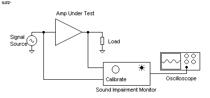
The version I have developed is analogue, and requires the best opamp possible to get good results. The connection of the SIM is shown in Figure 1, and it includes a LED to indicate that something interesting (i.e. bad) is happening. An oscilloscope can be connected to allow us to see exactly what is causing the problem, and the SIM can be used with normal programme material. Indeed, this is the whole idea, since it avoids all the criticism of static (sine wave) tests. The SIM will be just as revealing (and in some cases more so) with so-called "static" sinewave testing, since the exact distortion waveform will be quite visible. Square wave testing will also be very revealing. All amplifiers will show a difference between a fast rise-time square wave at the input versus output, but a modified (i.e. filtered to some agreed standard) square wave is still a very hard test on an amp, and may be helpful in identifying the problems that are supposedly audible, and isolating those that are not.

Figure 1 - Connecting
The SIM To An Amplifier
When the SIM is connected, a normal signal (at a normal to low level) is applied. The calibration controls are set to ensure that the LED is not lit and the monitor amp should be almost completely quiet. Sensitivity (not shown) is increased, and calibration is readjusted until the highest possible sensitivity is obtained with the LED not illuminated. Some experimentation will be needed to ensure that small phase differences do not cause the SIM to indicate a problem that does not exist, but initial testing indicates that this may be an extraordinarily useful test for amplifiers.
With the monitor amplifier, we will be able to hear any difference between the original and amplified signal, and for the very few amps with distortion that is low enough, this should be mainly noise. There will always be some signal present, but it should not sound at all like music since we are interested only in distortion products. Note that distortion covers everything in this context - frequency and phase response, amplitude variations, and actual distortion.
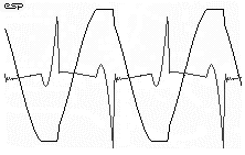
Any distortion (regardless of origin) that arises as the level is increased or changes are made to leads or other components will cause the LED to light, and we can observe the difference between input and output on the oscilloscope. Figure 2 shows the waveform we will obtain if the amplifier clips and has some degree of overhang ("power rail sticking") - a sinewave is shown for clarity, but the same principle applies with music.

Figure 2 - An Amplifier
With "Overhang" Clipping
Is this the perfect amplifier monitor? No. In some cases normal variations in input level will cause the LED to light, but the oscilloscope should show exactly what is happening. Any variation in the shape or sound (rather than the amplitude or volume) of the waveform indicates a problem, but it may not be possible with normal programme material to see the exact mechanism that is the root cause.
It is potentially a much better test than the standard tests we have seen a thousand times (all looking pretty much the same as each other), but are still unable to reveal everything. Perhaps someone out there with DSP programming skills will be able to do a better job than a simple analogue circuit can achieve, but even as it stands, it is better than the current methods. By how much? This remains to be seen ....
Or heard. The output of the SIM really should be monitored with headphones or a loudspeaker, so not only do we see the difference on an oscilloscope, but we can listen to the difference signal. In a perfect amplifier we will hear silence - there will be no difference at all, but in the real world we will always be able to hear and see a residual signal.
Here is where listening is important! The residual signal may have a hard "gritty" edge with an amplifier and one set of speaker leads (for example). By substituting the leads, this may become a "smooth" signal, which although bearing no resemblance to the actual music, has no harsh overtones or other nastiness. We can safely assume that the difference is beneficial, that the second set of leads really does improve the sound.
We still don't know why, but armed with some evidence we have at least a fighting chance of finding out.
I ran some tests on the SIM concept, with a normal signal and my 60W amp. The reaction to signal clipping was instant and highly visible. Even clipping that was of such magnitude and duration that I could not see it on the oscilloscope waveform of the amp's output showed up instantly, as will any other variation. Likewise, any signal that exceeds the amplifier's slew rate also shows up, but I had to deliberately slow the amp down by increasing the miller capacitance to see this.
If this amp had any form of protection, activation of the protection circuit would also show up as large spikes on the output waveform, so I am well satisfied that this is an extremely valid test. Unlike a clipping indicator, the SIM shows any deviation from the normal expected waveform, howsoever caused.
I found that phase shift at low frequencies (caused by the amp's input capacitor) made a good null very difficult, and after some experimentation I found that a high pass filter at the detector output tuned to about 700Hz eliminated the low frequency signal with no apparent loss of accuracy for signal impairment detection.
Next Steps - Involvement, Anyone?
I experimented with a square wave signal, and quite predictably the
SIM went crazy, indicating every level change. The rise and fall
time of my oscillator is very fast (it will give an excellent square wave
at 100kHz), so this was entirely expected. The same will happen with
almost any amp in the known universe, since few (if any) can reproduce
a square wave perfectly, especially when the input signal is as fast as
mine.
To be able to get an instant feel for an amp's ability to reproduce normal music, I suggest that for square wave testing with the SIM, a low pass filter be used, having a 6dB per octave rolloff from 1kHz. This will limit the harmonics to something passably sensible - it is still a severe test, and one that few amps will ace, because the SIM is so sensitive to any impairment to the signal - of amplitude or phase or any combination.
I am anxious to hear suggestions from anyone who might be interested in assisting with the development of a standard test method for amplifiers - one that will show the things we need to see, and reject those that are inaudible. The SIM is potentially the first real advance in amplifier testing methods for many years, and if properly implemented could become a standard test that can be included in all reviews.
For example, if standardised, we could have an oscilloscope trace of the SIM filtered square wave performance for each amp tested and reviewed, and if left connected to the review amp (without the filtered square wave, of course), will enable the reviewer to ensure that no protection circuit is activated and there is no clipping during the listening test. I suspect that a few people might be surprised at the results, as I was when I was sure that the amp was not clipping with an applied music signal (according to the oscilloscope), yet the SIM showed quite plainly that it was.
One of the best things about the SIM is that it is relatively cheap to build, requires minimal calibration other than compensating for the gain (and in some cases phase) of the amp under test, and shows up imperfections that occur in music and in "real time" - not just steady tones. As mentioned above, it will also show that protection circuits have activated, and can display the instantaneous magnitude of the error signal on a LED bar graph, peak programme meter or monitor speaker.
If it appears that I am a little excited by my findings so far, this is only because I am! Can anyone imagine the jubilation if the SIM were to show that the perceived differences in various amplifiers showed up clearly, and in a way that could be easily analysed.
Not only amplifiers themselves, but speaker leads, interconnects, and even mains leads will all show a difference if it exists - we might be able to eliminate some of the fierce debate that currently exists if it can be shown that the effects are real (or equally that they are not). All of this with real music, connected to real speakers and in real time.
There is not a test methodology currently used that has this capability, so you bet I'm excited. I am even prepared to give this technology away to anyone who wants to try it. A project for the internal SIM is already published, and the external SIM will be published when completed.
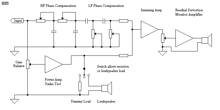
The idea of the external SIM is actually not new, having first been proposed by Peter Baxandall many years ago. The current design bears some similarity to the original, but there are important differences. The original Baxandall circuit is shown in Figure 3, but has a small problem in that the amplifier under test is expected to be inverting. This is very rare in modern designs, but in its time was relatively easy, since the amplifiers of the day were valve, and the polarity of the output transformer winding could simply be reversed. This is no longer possible.

Figure 3 - The Original
Baxandall Subtractive Test Set
Naturally enough, the term SIM was not applied to the original circuit, but name aside, I am puzzled as to why it never gained the popularity of "static" sine wave distortion testing (which is actually anything but static, a sine wave is a signal like any other, and stresses the amplifier in the same way as a music signal).
The original circuit proposed that gain and phase errors at high and low frequencies could be nulled by the compensation pots, and that the amplifier's gain would be equalised by adjusting the gain balance. Any residual signal would then be a direct representation of the distortion components in the amplifier. This residual may be monitored, and only the distortion components will be audible.
The Final New Design Criteria
Modern amplifiers will generally need minimal phase compensation, at
least within the audio range. Because of this, the circuit can be
simplified to some degree by reducing the phase nulling circuits to a single
pole each. The external SIM is based on this principle, and with
careful adjustment will allow very small differences to be heard (and seen
on an oscilloscope).
To reduce the loading on the input source, the final SIM will use a high grade opamp to buffer and invert the signal before the phase compensation circuits. This has the added advantage that it will also allow a better match to the amplifier because of the very small phase differences it will introduce itself. To verify that the input buffer is not a contributor to the residual signal, I will be setting up a calibrate switch, allowing the amp under test to be bypassed entirely and replaced by a direct connection.
To minimise any loading on the input, a unity gain buffer will also be incorporated. This may change the sound to a small degree in itself, but will not affect the validity of any comparisons done on the test amplifier, as it will be in circuit all the time. To completely eliminate mains interference, the SIM will be battery powered, but will drive an external small power amp for monitoring. This connection will be balanced to eliminate earth loops and hum injection back into the SIM and the amp under test.
The 700Hz filter I mentioned above is an option I will have to think about very carefully. I do think it is a good idea, but it should be able to be bypassed (or perhaps made variable).
As you can imagine, there is a lot of work to be done before the design is complete, and the basic criteria above are likely to change as I progress.
The internal SIM is published as Project 57, and can be applied to any amplifier. It does require that the amp be modified, and it is very important that leads are kept short and all wiring is carefully done so as not to adversely affect the amplifier. There is little point in an instrument that will show you how badly the amplifier performs when the instrument is connected!
The internal SIM is only capable of showing differences that occur within the amplifier itself, although in some cases the speaker leads may affect the calibration. Again, it is possible to use a small headphone amp to allow the residual signal to be monitored. Now when you change the stock mains lead for a set of nice new SupaTune9000s, you will hear the difference in the amplifier itself, if indeed any difference exists.
Is the difference good or bad? This is for you to determine, but at least you will know there is a difference. This is the first principle of experimentation. There must be an observable change in an amplifiers output for any difference to be heard. This much is plain. What is not plain (using conventional test methods) is how this can be detcted. The SIM might well be the missing link, revealing all (well, some, at least) to those who really want to know.