Copyright ![]() 2001 - Rod Elliott (ESP)
2001 - Rod Elliott (ESP)
Page Published & Updated
24 Mar 2001
Transformers - The Basics
Section 1

| Elliott Sound Products | Beginners' Guide to Electronics - Part 2 |
Copyright ![]() 2001 - Rod Elliott (ESP)
2001 - Rod Elliott (ESP)
Page Published & Updated
24 Mar 2001
Transformers - The Basics
Section 1
As you look through this article, you may be excused for exclaiming "This is for beginners? - the man's mad. Mad, I tell you!" This is probably fair comment, but transformers are not simple, and there is no simple way to provide all the information you need to understand them properly. There are sections here that probably go a little bit deeper than I originally intended, but were just too interesting to leave out.
There are parts of this article you may want to skip over, but I suggest that you do read all of it if you can. A full understanding to the extent where you can design your own transformer is not the aim, but the majority of the information is at the very least interesting, and will further your general electronics knowledge.
For those who wish to delve deeper, there is an additional article in progress that does just that. It is recommended reading, even for beginners, as there is a great deal to be learned about transformers, despite their apparent simplicity.
The principles that allow us to make use of electro-magnetism were only discovered in 1824, when Danish physicist Hans Oersted found that a current flowing through a wire would deflect a compass needle. A few years after this, it was found that a moving magnetic field induced a current into a wire. From this seemingly basic concept, the field of electromagnetism has grown to the point that society as we know it would not exist without the many machines that make use of these discoveries.
Transformers are essential for all modern electronics equipment, and there are very few devices that do not use them. Each transformer type has a specific use, and it is uncommon that a transformer made for one application can be used for another (quite different) purpose.
Before embarking on a description of the different types, the basic theory must be understood. All transformers use the same basic principle, and only the finer points ever change. A transformer works on the principle of magnetic coupling to transfer the energy from one side (winding) to the other.
Transformers are bi-directional, and will work regardless of where the input is connected. They may not work as well as they otherwise might, but basic functionality is unchanged. An ideal transformer imposes no load on the supply (feeding the primary) unless there is a load across the secondary - real life components have losses, so this is not strictly true, but the assumption can be used a a basis of understanding.
Power transformers are rated in Volt-Amps (VA). Using Watts is of no use, since a load that is completely reactive dissipates no power, but there are still Volts and Amps. It is the product of "real" voltage and current that is important - a wattmeter may indicate that there is little or no real power in the load, but the transformer is still supplying a voltage and a current, and will get hot due to internal losses regardless of the power.
Transformer cores have a quoted permeability, which is a measure of how well they "conduct" a magnetic field. Magnetism will keep to the path of least resistance, and will remain in a high permeability core with little leakage. The lower the permeability, the greater is the flux leakage from the core (this is of course a gross simplification, but serves well enough to provide an initial explanation of the term).
A transformer may be made with various materials as the core (the magnetic path). These include
Core materials are generally classified as "soft" - this has nothing to do with their physical properties (they are all hard to very hard), but is a reference to their ability to retain magnetism (remanence). Hard magnetic materials are used for magnets, and they have a very high remanence, which is to say they retain a very large proportion of the original magnetic field that was induced into them during manufacture.
All switchmode power supplies use ferrite transformers, since conventional laminations cannot be made thin enough to prevent huge losses in the core.
Many limitations exist in any core material. For low frequency power applications, grain-oriented silicon steel (about 4% silicon) is by far the most common, as it has a very high flux density before saturation. Almost all other materials are inferior in this respect, one of the main reasons this material is still so common.
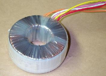
Toroidal![]()
![]()
![]()
![]()
![]()
![]()
![]()
![]()
![]() E-I
E-I
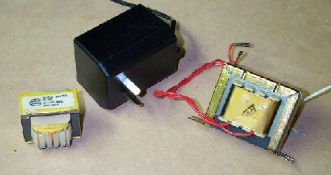
Split Bobbin E-I![]()
![]() Plug-Pack
Plug-Pack![]()
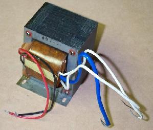
![]() Conventional
E-I
Conventional
E-I
A small sample of some transformers is shown above (not to scale). The toroidal and E-I transformers are the same power rating, and a small selection of little transformers and a plug-pack (wall transformer, wall-wart, etc) are shown as well.
The transformer is essentially just two (or more) inductors, sharing a common magnetic path. Any two inductors placed reasonably close to each other will work as a transformer, and the more closely they are coupled magnetically, the more efficient they become.
When a changing magnetic field is in the vicinity of a coil of wire (an inductor), a voltage is induced into the coil which is in sympathy with the applied magnetic field. A static magnetic field has no effect, and generates no output. Many of the same principles apply to generators, alternators, electric motors and loudspeakers, although this would be a very long article indeed if I were to cover all the magnetic field devices that exist.
When an electric current is passed through a coil of wire, a magnetic field is created - this works with AC or DC, but with DC, the magnetic field is obviously static. For this reason, transformers cannot be used directly with DC, for although a magnetic field exists, it must be changing to induce a voltage into the other coil.
Try this experiment. Take a coil of wire (a loudspeaker crossover coil will do nicely for this), and a magnet. Connect a multimeter - preferably analogue) to the coil, and set the range to the most sensitive current range on the meter. As you move the magnet towards or away from the coil, you will see a current, shown by the deflection of the meter pointer. As the magnet is swung one way, the current will be positive, the other way - negative. The higher the coil's inductance and the stronger the magnet (and/ or the closer it is to the coil), the greater will be the induced current.
Move the magnet slowly, and the current will be less than if it is moved quickly. Leave it still, and there is no current at all, regardless of how close the magnet may be. This is the principle of magnetic induction, and it applies to all coils (indeed to all pieces of wire, although the coil makes the effect much greater).
If you now take a handful of nails and place them through the centre of the coil, you will see that the current is increased many times - the magnetic field is now more concentrated because the steel nails make a better magnetic path than air.
The ability of a substance to carry a magnetic field is called permeability, and different materials have differing permeabilities. Some are optimised in specific ways for a particular requirement - for example the cores used for a switching transformer are very different from those used for normal 50/60Hz mains transformers.
The permeability of transformer cores varies widely, depending on the material and any treatment that may be used. The permeability of air is 1, and most traditional cores have a much higher (i.e. > 1) permeability. A couple of notable exceptions are aluminium and brass, which are sometimes used to reduce the inductance of air cored coils in radio frequency (RF) work. This is much less common than a ferrite "slug" core, which increases the inductance and is used to tune some RF transformers.
As well as permeability, magnetic cores (with the exception of air) have a maximum magnetic flux they can handle without saturation. In this context, saturation means the same as in most others - when a towel is saturated, it can hold no more water, and when a magnetic core is saturated, it can carry no more magnetic flux. At this point, the magnetic field is no longer changing, so current is not induced into the winding.
You will be unable to saturate your nails with the magnet, as there is a very large air gap between the two pole pieces. This means that the core will always be able to support the magnetic flux, but the efficiency is also very much lower because the magnetic circuit is open. Nearly all the transformers you will see have a completely closed magnetic circuit, to ensure that as much of the magnetism induced into the core as possible will pass through the winding(s).
There are some cases where a tiny air gap will be left deliberately, and this is done routinely when a transformer or coil must sustain a significant DC component as well as the AC. This is covered briefly below, but there is more on this subject in the second section of the article.
Figure 1.1 - Essential
Workings of a Transformer
Figure 1.1 shows the basics of all transformers. A coil (the primary) is connected to an AC voltage source - typically the mains for power transformers. The flux induced into the core is coupled through to the secondary, a voltage is induced into the winding, and a current is produced through the load.
The diagram also shows the various parts of a transformer. This is a simple transformer, with two windings. The primary (denoted as such during the design) will induce a magnetic field into the core in sympathy with the current produced by the applied AC voltage. The magnetic field is concentrated by the core, and nearly all of it will pass through the windings of the secondary as well, where a voltage is induced. The core in this case is typical of the construction of a "C-Core" transformer, where the primary and secondary are separated. More common is the "traditional" EI (ee-eye) type, which although somewhat out of favour these days is still used extensively. This is shown below.
The magnitude of the voltage in the secondary is determined by a very simple formula, which determines the "turns ratio" (N) of the component - this is traditionally calculated by dividing the secondary turns by the primary turns ...
| N = Ts / Tp |
Tp is simply the number of turns of wire that make up the primary winding, and Ts is the number of turns of the secondary. A transformer with 500 turns on the primary and 50 turns on the secondary has a turns ratio of 1:10 (i.e. 1/10 or 0.1)
| Vs = Vp * N |
Mostly, you will never know the number of turns, but of course we can simply reverse the formula so that the turns ratio can be deduced from the primary and secondary voltages ...
| N = Vs / Vp |
If a voltage of 240V (AC, naturally) is applied to the primary, we would expect 24V on the secondary, and this is indeed what will be measured. The transformer has an additional useful function - not only is the voltage "transformed", but so is the current.
| Is = Ip / N |
If a current of 1A were drawn by the primary in the above example, then logically a current of 10A would be available at the secondary - the voltage is reduced, but current is increased. This would be the case if the transformer were 100% efficient, but even this - the most efficient "machine" we have - will sadly never be perfect. With large transformers used for the national supply grid, the efficiency of the transformers will generally exceed 95%, and some will be as high as 98% (or even more).
Smaller transformers will always have a lower efficiency, but the units commonly used in power amplifiers can have efficiencies of up to 90% for larger sizes. The reasons for the lost power will become clear (I hope) as we progress. For the time being, we shall consider the transformer to be "ideal" (i.e. having no losses) for simplicity.
Figure 1.2 - E-I Laminations
The conventional E-I lamination set is still extensively used, and a few pertinent points are worth mentioning. The centre leg is always double the width of the outer legs to maintain the cross-sectional area. Likewise, the "I" lamination and the "back" of the E are the same width as (or sometimes slightly larger than) the outer legs. The winding window is where the copper windings live, and in a well designed transformer will be almost completely full. This maximises the amount of copper and reduces resistive losses because the windings are as thick as they possibly can be.
This list is far from complete, but will be sufficient to either get you started or scare you away. I have included the symbols and units of only three of the entries below, since most are of no real interest.
Coercivity - is the field strength which must be applied to reduce (or coerce) the remanant flux to zero. Materials with high coercivity (e.g. those used for permanant magnets) are called hard. Materials with low coercivity (those used for transformers) are called soft.
Effective Area - of a core is the cross sectional area of the centre limb for E-I laminations, or the total area for a toroid. Usually this corresponds to the physical dimensions of the core but because flux may not be distributed evenly the manufacturer may specify a value which reflects this.
Effective length - of a core is the distance which the magnetic flux travels in making a complete circuit. Usually this corresponds closely to the average of the physical dimensions of the core, but because flux has a tendency to concentrate on the inside corners of the path the manufacturer may specify a value for the effective length.
Flux Density - (symbol; B, unit; teslas (T)) is simply the total flux divided by the effective area of the magnetic circuit through which it flows.
Flux linkage - in an ideal inductor the flux generated by one turn would be contained within all the other turns. Real coils come close to this ideal when the other dimensions of the coil are small compared with its diameter, or if a suitable core guides the flux through the windings.
Magnetomotive Force - MMF can be thought of as the magnetic equivalent of electromotive force. It is the product of the current flowing in a coil and the number of turns that make up the coil.
Magnetic Field Strength - (symbol: H, unit; ampere metres (A m-1)) when current flows in a conductor, it is always accompanied by a magnetic field. The strength, or intensity, of this field is proportional to the amount of current and inversely proportional to the distance from the conductor (hence the -1 superscript).
Magnetic Flux - (symbol: ![]() ;
unit: Webers (Wb)) we refer to magnetism in terms of lines of force or
flux, which is a measure of the total amount of magnetism.
;
unit: Webers (Wb)) we refer to magnetism in terms of lines of force or
flux, which is a measure of the total amount of magnetism.
Permeability - (symbol; µ, units: henrys per metre (Hm-1) is defined as the ratio of flux density to field strength, and is determined by the type of material within the magnetic field - i.e. the core material itself. Most references to permeability are actually to "relative permeability", as the permeability of nearly all materials changes depending upon field strength (and in most cases with temperature as well).
Remanence - (or remnance) is the flux density which remains in a magnetic material when the externally applied field is removed. Transformers require the lowest possible remanence, while permanant magnets need a high value of remanence.
I mention these here for the sake of completeness, but their real importance is not discussed further in Section 1. Section 2 of this article will revisit the terms, and their importance is somewhat enhanced in context.
At no load, an ideal transformer draws virtually no current from the mains, since it is simply a large inductance. The whole principle of operation is based on induced magnetic flux, which not only creates a voltage (and current) in the secondary, but the primary as well! It is this characteristic that allows any inductor to function as expected, and the voltage generated in the primary is called a "back EMF" (electromotive force). The magnitude of this voltage is such that it almost equals (and is effectively in the same phase as) the applied EMF.
No simple calculation can be made to determine the internally generated voltage. As described in Part 1 of this series, for a sinusoidal waveform, the current through an inductor lags the voltage by 90 degrees. Since the induced current is lagging by 90 degrees, so too is the induced voltage (back EMF). For the sake of simplicity, imagine an inductor or transformer (no load) with an applied voltage of 100V. For the effective back EMF to equal the applied AC voltage (as it must), the actual magnitude of the induced voltage (back EMF) is 141V. If this is all to confusing, don't worry about it. Unless you intend to devote your career to transformer design, the information is actually of little use to you, since you are restrained by the "real world" characteristics of the components you buy - the internals are of little consequence. Even if you do devote your life to the design of transformers, this info is still merely a curiosity for the most part, since there is little you can do about it.
When you apply a load to the output (secondary) winding, a current is drawn by the load, and this is reflected through the transformer to the primary. As a result, the primary must now draw more current from the mains. Somewhat intriguingly perhaps, the more current that is drawn from the secondary, the original 90 degree phase shift becomes less and less as the transformer approaches full power. The power factor of an unloaded transformer is very low, meaning that although there are volts and amps, there is relatively little power. The power factor improves as loading increases, and at full load will be close to unity (the ideal).
Now, another interesting fact about transformers can now be examined.
We will use the same example as above. A 240V primary draws 1A, and the 24V secondary supplies 10A to the load. Using Ohm's law, the load resistance (impedance) is therefore 24/10 = 2.4 Ohms. The primary impedance must be 240/1 = 240 Ohms. This is a ratio of 100:1, yet the turns ratio is only 10:1 - what is going on?
The impedance ratio of a transformer is equal to the square of the turns ratio ...
| Z = N2 |
Transformers are usually designed based on the power required, and this determines the core size for a given core material. From this, the required "turns per volt" figure can be determined, based on the maximum flux density that the core material can support. Again, this varies widely with core materials.
A rule of thumb can be applied, that states that the core area for "standard" (if indeed there is such a thing) steel laminations (in square centimetres) is equal to the square root of the power. Thus a 625VA transformer would need a core of (at least) 25 sq cm, assuming that the permeability of the core were about 500, which is fairly typical of standard transformer laminations. This also assumes that the core material will not saturate with the flux density required to obtain this power.
The next step is to calculate the number of turns per volt for the primary winding. This varies with frequency, but for a 50Hz transformer, the turns per volt is (approximately) 45 divided by the core area (in square centimetres). Fewer turns are needed for a 60Hz transformer, and the turns per volt will be about 38 / core area. Higher performance core materials may permit higher flux densities, so fewer turns per volt might be possible, thus increasing the overall efficiency and regulation. These calculations must be made with care, or the transformer will overheat at no load.
For a 625VA transformer, it follows that you will need about 432 turns for a 240V primary, although in practice it may be less than this. The grain-oriented silicon steels used in better quality transformers will often tolerate much higher total flux per unit area, and fewer turns will be needed.
You can determine the turns per volt of any transformer (for reasons that will become clearer as we progress) by adding exactly 10 turns of thin "bell wire" or similar insulated wire to an existing transformer, wound over the existing windings. When powered from the correct nominal supply voltage, measure the voltage on the extra winding you created, and divide by 10 to obtain the turns per volt rating for that transformer.
Now, what earthly use is this to you? Well, you might be surprised at what you can do with this knowledge. Assume for a moment that you have a transformer for a fair sized power amplifier. The secondary voltage is 35-0-35V which is much too high to power the preamp circuit or even its power supply - but you will be able to do that with a single 16V winding. Another transformer would normally be used, but you can also add the extra winding yourself. This is almost too easy with toroidal transformers, but with others it may not be possible at all. If the transformer uses (say) 2 turns per volt, a mere 32 extra turns of bell wire (or similar) will provide 16V at the typical 100mA or so you will need. Add a 10% margin, and you still have only 36 turns to add, and this can be done in a few minutes. Make sure that the extra winding is securely taped down with a good quality tape (Kapton is highly recommended if you can get it). Do not use ordinary electricians' tape - it is not designed for the temperature that transformers may operate at under consistent load.
NOTE: Ensure that there is no possibility whatsoever of the added winding shorting between turns - this will cause the smoke to escape from the insulation in a spectacular fashion, and you may ruin the transformer itself.
As discussed above, the impedance ratio is the square of the turns ratio, but this is only one of many interesting things about transformers (well, I think they are interesting, anyway :-)
For example, one would think that increasing the number of turns would increase the flux density, since there are more turns contributing to the magnetic field. In fact, the opposite is true, and for the same input voltage, an increase in the number of turns will decrease the flux density and vice versa. This is counter-intuitive until you realise that an increase in the number of turns increases the inductance, and therefore reduces the current through each coil.
I have already mentioned that the power factor (and phase shift) varies according to load, and this (although mildly interesting) is not of any real consequence to most of us.
A very interesting phenomenon exists when we draw current from the secondary. Since the primary current increases to supply the load, we would expect that the magnetic flux in the core would also increase (more amps, same number of turns, more flux). In fact, the flux density decreases! In a perfect transformer with no copper loss, the flux would remain the same - the extra current supplies the secondary only. In a real transformer, as the current is increased, the losses increase proportionally, and there is slightly less flux at full power than at no load.
This is only a brief discussion of the many uses of transformers. I have avoided switchmode supplies in this section, and will only present the most common linear applications. Power supply applications are covered more fully in Section 2, and also in the article on Linear Power Supply Design.
It would be impossible to cover all aspects of transformers and their uses, since they are so diverse and are used in so many different things. Computer network interface cards, modems, through to power amplifiers and microwave ovens, car and marine ignition systems, Tesla coils and moving coil phono preamps are a very small sampling of the diversity of the humble transformer (well, maybe it is not so humble after all :-)
5.1
- Push-Pull Valve Output Stage
Apart from the obvious uses in power supplies, transformers are used
in other areas as well. Valve power amplifiers nearly all use a transformer
for the output stage, and this converts the high impedance of the anodes
to the loudspeaker impedance, as well as providing the voltage feed to
the output valves. No biasing or other support components have been
shown here - for more information on this, have a look at How
Amplifiers Work.
Figure 5.1 - Push-Pull
Valve Output Stage
Figure 5.1 shows how this works. The primary winding acts in a manner that may surprise you at first, but it is quite in accordance with all the theory. The supply voltage shown is 500V, and we will assume that the valve can turn on hard enough to reduce this to zero alternately at each end of the winding. This is never the case, because valves do not have a low enough internal impedance, but it makes the explanation simpler :-)
Neither valve will draw appreciable current with no signal, and the amount drawn does not magnetise the core. The reason is simple - an equal amount of current is drawn through each section of the primary winding, but effectively in opposite directions. The magnetic field created by one half of the winding is cancelled by that from the second half, leaving a nett steady state magnetic field of zero.
When valve V1 turns on completely, the voltage at its end of the winding is reduced to zero, and the voltage at the anode of V2 is 1,000 volts. This must be the case, or the transformer theory is in tatters. The primary is operating as an "auto-transformer". Likewise, when V1 turns off and V2 turns on, the situation is reversed. You may well ask why 2 valves are needed at all? The voltage from one valve is quite capable of swinging the voltage from one extreme to the other, it would seem.
This is not the case. Since the valve can only turn on, it will only be able to supply current for 1/2 of the waveform. A Class-A push-pull design will normally have each valve carrying 1/2 of the maximum peak current required. In the case of a push-pull design, there is no core saturation because of the DC current (which cancels out as before), so although two valves are needed, the transformer will be smaller and will have very much better performance. Single-ended Class-A amps require a very large core with an air-gap to prevent saturation. This reduces the performance of the transformer dramatically, and increases distortion and gives a poorer low frequency response because of the lower inductance. High frequencies can also be adversely affected, because the air-gap causes some of the magnetic flux to "leak" out of the core. This is the cause of leakage inductance (covered in more detail in Section 2).
It is worth noting that the effective peak to peak swing across the entire transformer primary is 2,000V. When V1 is turned on completely, it has zero volts (for our example only) at the plate, and V2 turns on it has a plate voltage of 1,000V. V2 has exactly the same voltage peaks, but they are 180 degrees out of phase. The total voltage across the transformer is therefore the sum of the two voltages. From an AC perspective, the B+ supply line can be considered the same as zero volts (remember it will be bypassed with a large capacitance).
The RMS voltage is easily calculated from the standard formula ...
| Vp = Vp-p / 2 | Obtain the peak value from peak to peak | |||
| Vrms = Vp / |
Then the RMS value |
In this case, the peak to peak voltage is 2,000V, so peak is 1000V. The RMS value is 707V.
5.2 Single
Ended Triode (SET) Output
Figure 5.2 shows the basic arrangement of a SET amplifier output stage.
The full DC current must flow through the transformer primary, and as discussed
above, an air-gap must be introduced into the core to prevent saturation.
Because an air gap reduces the efficacy of the magnetic path, the core
needs to be considerably larger than would otherwise be the case.
Figure 5.2 - Single Ended
Triode Output Stage
The core operates with only one polarity of flux, which varies with the signal. One might think that this alone would reduce distortion, since the flux never crosses the zero point, but this is not the case. It is still necessary for the flux to change, and the characteristics of magnetic materials indicate that the resistance to change (rather than the absolute polarity of the magnetic field) is the dominant factor. The valve (and transformer primary) must now carry a current equal to the peak AC current demanded by the load - subject to the transformation ratio, of course. Maximum negative swing (valve turned on) will double this current, and it will be reduced to nearly zero as the valve turns off (positive swing). As the current is reduced below the average standing (quiescent) current, the voltage across the transformer increases in the opposite polarity - hence the fact that the plate voltage exceeds the supply voltage.
For the same power output, the valve in a single ended circuit must be considerably larger than that required for a push-pull circuit, because of the higher dissipation needed for the extra current. There are also many other issues with this arrangement, and they will be covered in more detail in Section 2.
Not the least of these is that the (probable) advantage of the additional voltage swing when using a centre tapped transformer is now gone, so the maximum RMS voltage that can be developed is 353V - a significant drop in primary AC voltage.
5.3
Line Level Applications
Transformers are also used for "line-level" low power applications,
typically balanced microphone inputs and line output stages. A transformer
is unsurpassed for real-world balanced circuits, as the input or output
is truly floating, and requires no connection to earth. This means
that common mode signals (i.e. any signal that is common to both signal
leads) are almost completely rejected.
Figure 5.3 shows a transformer balanced input, converting to unbalanced. The signal is amplified, and sent to the output transformer for distribution as a balanced signal again. The "amplifier" will typically be a mixing console, and will take mic or line level signals as the input (having run from the stage to the mixing area), and the final mixed output is sent back to the stage for the main (Front of House) public address amplifiers and speakers. There may be in excess of 100 metres of cable from the microphone to the mixer and back to the main amps, and barely any noise will be picked up in the process.
Figure 5.3 - Balanced
Microphone and Line Outputs
The telephone system used to be completely dependent on transformers to feed the signal from the exchange (or Central Office in the US) to the customer premises equipment (CPE). The phone switch used in offices, (PABX - Private Automatic Branch Exchange, or PBX for the US) equipment still uses transformers for nearly all incoming circuits whether analogue or digital. The principle is exactly the same as for the audio application shown above, except that for telephone circuits there is usually a DC voltage present to power the CPE (in the case of a home telephone) and to provide some basic signalling. All modern PABX circuits use ferrite cored transformers, with DC isolation circuitry to ensure that no DC flows in the transformer windings, as this degrades the performance in the same way as with the output transformer for a SET power amplifier.
Audio applications for transformers in balanced circuits came from the telecommunications industry where the concepts were first thought of. A telephone line may be 4km or more in length, and is not shielded, so a method of eliminating hum and noise was essential.
Safety is a major consideration for any power transformer (and in the case of telecommunications, the isolating transformers), and electrical contact between primary and secondary must not be allowed under any realistic fault condition. All countries have safety standards that apply to transformers where electrical isolation is important, and if in any doubt about the safety of a transformer for a particular purpose, make sure that you verify that the transformer complies with the relevant standard(s). It is well beyond the scope of this article to cover all the possibilities of standards and compliance issues, so I shall leave that to you.
Many power transformers are fitted with an internal "once only" thermal fuse that will become open circuit in the event that a preset temperature is exceeded. This temperature is chosen to be the maximum safe temperature of the windings before the insulation melts or breaks down, so in the event of a fault, the thermal fuse will open before the insulation is damaged and the component becomes potentially dangerous. It also helps to prevent the risk of fire (and no, this is not intended to be humourous - a friend of mine had his house burned to the ground because of a faulty power transformer in a video recorder - as determined by the fire investigators. True story!). See Figure 6.1 (below) as an example of how bad things can get if the transformer is not protected.
Once the thermal fuse opens, the transformer must be discarded, as it is usually not possible to gain access to the fuse for replacement. This is not as silly as it may sound, since the thermal effects on the insulation cannot be predicted, and the transformer may be unsafe if it were still able to be used.
There are transformers that are designed to be "intrinsically safe", and these usually have the windings on separate sections of the core, not in physical contact with each other. If the core is connected to the electrical safety earth (which is usually a requirement), no method of failure (including a complete meltdown) in the primary will allow mains voltage to appear at the secondary. Side by side windings are the next safest, and although primary and secondary are on the same bobbin, the material used is selected to withstand high temperatures and will maintain separation of the windings. Toroidal cores and other concentrically wound transformers are the least safe, since the only separation between primary and secondary is a rather thin layer of insulation. This is one of the reasons that thermal fuses are often used with toroids.
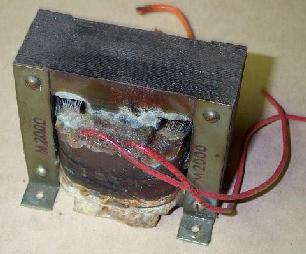
Figure 6.1 - Transformer
Meltdown
Figure 6.1 shows a transformer I removed from a repair job. It is a complete meltdown, and the remains of the plastic bobbin can be seen quite clearly. In any circuit, it is extremely important to protect the user from coming into contact with the mains should this happen. In this case, the bobbin had melted away from the windings, dribbled on the base of the equipment, and generally made a big mess. Despite all this, there was no electrical connection between primary and secondary or the laminations. This was a well made transformer (it failed due to gross continuous overload, not any failure in the transformer itself).
Proper safety earthing is the only real way to ensure that a transformer that fails catastrophically (such as that shown) does not cause the chassis to become live - not all transformers are created equal when safety is concerned. Correct fusing will ensure that the fuse blows - hopefully before the electrical safety is compromised. A thermal fuse would have prevented the situation from becoming as bad as shown, but the transformer would have been just as dead.
Transformers make noise. This is not only the electrical noise that is created by the nasty current waveform through the windings, diodes and into the filter capacitors, but actual audible noise. One source is winding vibration, due to the wire moving because of the magnetic field and the current flowing through the conductors. This is to be avoided at all costs, since constant vibration will eventually wear away the insulation, the windings will short circuit, and the transformer is ruined. Fortunately, this is rather unusual, but it can (and does) happen on occasion.
Most of the noise is from the laminations or other core material, which contract when subjected to an intense magnetic field. This is called magnetostriction, and happens to a greater or lesser degree with all magnetic materials. A stethescope will verify the source of the noise, and there is little or nothing that will stop it. A resilient mounting will stop most of the noise from being acoustically amplified by the chassis, and generally the noise will be worse at no load. In some cases, a transformer may have been designed for 60Hz, but is used at 50Hz. In this case, the flux density will probably exceed the maximum allowable for the core, and the transformer will get much hotter than it should, and will almost certainly be a lot noisier as well. Toriodal transformers will generally be much quieter than EI laminated (i.e. conventional) types.
Most (all?) transformers designed specifically for 60Hz will eventually fail with 50Hz mains, due to overheating. The reverse is not true, and 50Hz transformers can be operated quite safely on 60Hz.
Another problem with E-I laminations is that they may not have been fastened together well enough, and this allows the outer laminations in particular to vibrate. Better quality conventional transformers will commonly be impregnated with varnish (sometimes under vacuum) and baked in a moderate oven until tender .... oops, I mean until the varnish is completely dry. This binds the laminations and windings together, preventing noise, and also making the transformer more resistant to damage by water or other contaminants, and/ or under conditions of high humidity (such as in the tropics).
Click here to view the second part of the article. As I am sure you have noticed, transformers are not so simple after all.
These references are common to both sections of the article, although most only apply to Section 2. Countless different Web pages were researched during the compilation of these articles, and although some were interesting, the majority were of minimal use. Of those who I actually remember (a daunting task in itself, considering the sheer amount of searching I had to do), I must "thank" the following Web pages (in alphabetical order) ...
The following (slightly edited) definitions are from Units of Measurement
Units of Measurement site copyright by Russ Rowlett and
University of North Carolina at Chapel Hill.
Definitions used by permission.
tesla (T) - flux density (or field intensity) for magnetic fields (also called the magnetic induction). The intensity of a magnetic field can be measured by placing a current-carrying conductor in the field. The magnetic field exerts a force on the conductor which depends on the amount of the current and the length of the conductor. One tesla is defined as the field intensity generating one newton of force per ampere of current per meter of conductor. Equivalently, one tesla represents a magnetic flux density of one weber per square meter of area. A field of one tesla is quite strong: the strongest fields available in laboratories are about 20 teslas, and the Earth's magnetic flux density at its surface, is about 50 microteslas (µT). One tesla equals 10,000 gauss. The tesla, defined in 1958, is named after Nikola Tesla (1856-1943), whose work in electromagnetic induction led to the first practical generators and motors using alternating current (much to the annoyance of Edison, who claimed DC was "safer").
weber (Wb) - magnetic flux. "Flux" is the rate (per unit of time) in which something crosses a surface perpendicular to the flow. In the case of a magnetic field, then the magnetic flux across a perpendicular surface is the product of the magnetic flux density, in teslas, and the surface area, in square metres. If a varying magnetic field passes perpendicularly through a circular loop of conducting material (one turn), the variation in the field induces a electric potential in the loop. If the flux is changing at a uniform rate of one weber per second, the induced potential is one volt. This means that numerically the flux in webers is equal to the potential, in volts, that would be created by collapsing the field uniformly to zero in one second. One weber is the flux induced in this way by a current varying at the uniform rate of one ampere per second. The unit honours the German physicist Wilhelm Eduard Weber (1804-1891), one of the early researchers of magnetism.