
| Elliott Sound Products | The Design of Heatsinks |
Rod Elliott, ESP
Page Last Updated 18 Feb
2001
Introduction
Types of Heatsinks
Sample Calculations
Transistor Case Styles
Junction to Case Thermal Resistance
Case to Heatsink Thermal Resistance
Mica
Thermal Compounds
Thermal Inertia
Minimising Thermal ResistanceFurther Reductions of Thermal ResistanceIntroduced Thermal Resistance
Some Additional Thoughts
Flat-Pack Transistors
Where to Mount Transistors
Heatsink Surface Area
Altitude
Fin Density
Water Cooling
Heat Pipes
The Bottom Line
Other Heatsink Information
References
This article is essential reading for anyone
who uses heatsinks in audio, and the same principles apply for power control
and RF, as well as many other applications in electronics. There
are many misunderstandings and misconceptions about transistor mounting.
What are the essential requirements? Which things make the biggest
difference? These questions may not have occurred to many readers,
but they are very important to ensure the long term reliability of your
projects.
| Please ... read all of this article - not just the bit you think you need. You would be surprised how much I learned while researching and writing this material, and I have had a lot of additional information supplied by readers (you know who you are, and thank you for your input). The material here is the result of a lot of hard work, research, personal experience and (what should be) common knowledge. |
The design of heatsinks, or to be more exact for most builders, the selection of a suitable heatsink, is not difficult once the basics have been mastered. Terms such as 'thermal resistance' and 'degrees C / Watt' are a little daunting for the uninitiated, and the purpose of this article is to explain how thermal transfer works, from the transistor die until it is finally dispersed into the atmosphere.
This sort of information seems to be unusually difficult to obtain, either on the web or elsewhere, and I have had great difficulty in getting thermal resistance data from anywhere - although as you shall see as you read on, I have managed it. Not that this article is the "last word" on heatsinks - far from it, but it is a collection of some of the most useful information I have been able to gather thus far.
Note that in this article, the 'transistor' can be a bipolar, MOSFET or any other semiconductor device (including diodes or ICs of any sort) that is mounted in a case which must then be mounted on a heatsink of some description.
The reliability and longevity of any semiconductor device is (roughly) inversely proportional to the square of the junction temperature change. Thus halving the junction temperature will result in approximately 4 times the expected life of the component. The converse is also true! A worthwhile increase in reliability and component life can be achieved by a relatively small reduction in operating temperature, since these parameters increase exponentially as temperature is reduced.
The whole process of removing heat from a transistor's active area (the die or 'junction') involves many separate thermal transfers, and we shall examine each in turn. In order to see a meaningful result, we need a heat input value and an ambient air temperature. From these two basic elements, the entire heat flow can be established.
Towards this end, an electrical analogue may be drawn, showing the thermal generator as a current source, thermal resistance as a resistor and the thermal inertia (or transient capacity) of the various materials as a capacitor. The transient capacity is the ability of any material to absorb a quantity of heat for a short time, after which its temperature will rise in the same way as the voltage rises in a capacitor if the supply current is maintained.
Figure 1 - Heat Flow
From Generator To Ambient
From Figure 1, we can see the thermal resistance (Rth) from junction to case, the thermal inertia of the junction (this is very small), the thermal inertia of the case itself (again, not large), the thermal resistance from the case to the heatsink, thermal inertia of the heatsink (this might be very large) and finally the thermal resistance from the heatsink to ambient.
The small thermal inertia values should be ignored, as they will heat up very rapidly, and the heatsink itself will only absorb so much heat. A state of equilibrium is required where the heat input equals the heat output, but without the junction temperature reaching a dangerous level - even momentarily.
Heat sinks can be classified in terms of
manufacturing methods and their final form shapes. The most common types
of air-cooled heat sinks include:
Let us assume that the heat generated in the transistor die is 50W, such as might be the case with a Class-A power amplifier operating from a +/-25V supply, and drawing 2A quiescent current. Only half the total supply voltage of 50V is across the transistor in the quiescent or no signal state when the output is at zero volts, so each of the transistors in the output stage will have a voltage of 25V at 2A, or 50W dissipation.
An ambient temperature of 25 degrees C is a good starting point, and provides a safety margin for most domestic systems, although as we shall see later on, it is important to design for worst case if reliability is to be maintained.
The primary aim of the heatsink designer is to ensure that the total thermal resistance is kept to the minimum possible value, and the entire design process looks at thermal resistance as the primary item to be calculated. Only after this has been determined can the actual temperature of the transistor junction be predicted.
To some extent, this article was prompted by a reader of my pages, who complained that transistors in an amp he built ran very hot (mounted on a bracket), while others seemed to run fairly cool. So I got to thinking, didn't I?
How to actually mount transistors does not seem to have achieved much coverage on the web, but I have seen some absolute drivel spouted by PC types talking about heatsinking Pentium processors - the same principles apply, but the amount of heat and thermal dynamics are a little different.
Throughout this article I will often refer to "aluminium", which in this context means aluminium alloy. Pure aluminium is rarely used, since it is too soft and easily distorted. It is also quite difficult to drill and tap for mounting screws, because it tends to clog the flutes on the drill bit, and will even snap the drill if great care is not taken.
When drilling aluminium (or any of its alloys), the use of methylated spirit or WD40 (or other similar "water displacement" spray) as a lubricant is recommended. This trick is not well known, but is very effective.
Be warned that "metho" (as it is commonly known in Australia) is highly flammable, and burns with an almost invisible - but very hot - flame. Extreme care is required, and use only enough to keep the drill bit wet - the last thing we need is one of my readers burning down the house while drilling a heatsink. Needless to say, I can accept no responsibility for any accident caused by the use of this technique.
There is a vast number of different case
styles available. I shall only deal with the most common (as shown below),
but the information is equally valid for other case styles. In many cases,
an educated guess will be needed to determine case to heatsink thermal
resistance if the case used by your device is wildly different from those
quoted. Generally, this is based on surface area and the evenness (or otherwise)
of pressure distribution directly beneath the internal silicon die. This
is a wildly variable quantity, and has been known to cause may a constructor
grief, not realising the importance of evenly distributed pressure.
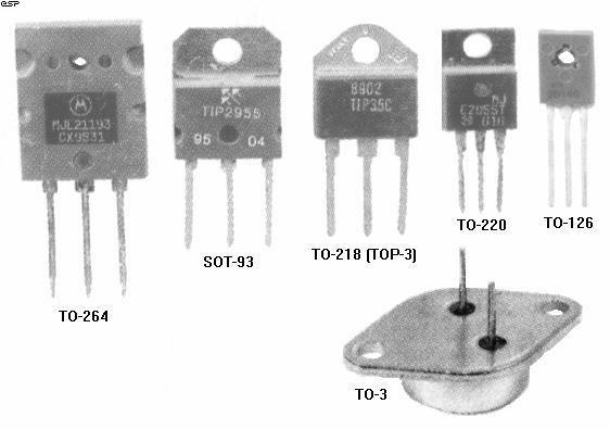
Figure 2 - Common Case
Styles
This is only a sample of those currently available (including ICs of various types), but is representative of the most common for transistors, MOSFETs and the like. In most cases, the die can be assumed to be roughly in the middle of the plastic moulding for all plastic encapsulated devices. In the TO-3 package, it is located in the geometric centre of the package (more or less).
Although this is always an important consideration, there is nothing the amplifier designer can do to reduce this for any given transistor. Manufacturer's data will sometimes quote this figure, but it is more common to refer to the device case temperature - this is easier to deal with, since the data sheets have already taken die to case thermal resistance into consideration when the temperature derating graph was produced.
Derating is commonly applied to semiconductor devices, and typically the maximum power dissipation claimed for most devices will be at or below 25 degrees C. At any temperature above this, less power is available from the transistor with increasing temperature, until at some figure (typically around 150 degrees) the permissible power dissipation is zero.
Figure 3 - Case Temperature
Derating For MJE3055
Figure 3 shows the case temperature derating curve for an MJE3055 (TO-220) power transistor as an example. As can be seen, at 25 degrees and below, the device is rated at 75W dissipation, but at 100 degrees, 30W is the maximum permissible. At 150 degrees, no power may be dissipated at all.
This device has a 1.67oC thermal resistance from junction (die) to case (Motorola specification sheet for the MJE2955/3055), so the actual junction temperature will be somewhat higher than the case temperature until 150 degrees, at which no power may be dissipated, so case and junction will be at the same temperature.
Our first calculation shall be to see what the junction temperature will be at 75W device dissipation, with the case at 25 degrees (Celcius):
If the junction is 125 degrees above ambient (25 degrees) then the total is 125 + 25 = 150 degrees
The information above is obtainable from all device manufacturers, and is essential reading to ensure that transistors are not damaged by excess temperature. The maximum quoted temperature should never be exceeded, as the device will have a considerably lower life expectancy if overheated. Instantaneous failure is not uncommon if a device at an already elevated temperature is called upon to suddenly do some work.
Using our theoretical amplifier above, we know that the dissipation will be 50W per transistor (or a total of 100W), and from the derating curve we see that for this power, the maximum case temperature is 65° C. The goal of this exercise is to determine the size of heatsink needed to ensure that the transistors ratings are not exceeded. We can also see if it is possible to operate them at a lower temperature, thus prolonging their operating life.
The junction to case thermal resistance varies widely, but will rarely be less than about 0.5 degrees C/W, depending (of course) on the manufacturer, the case style, and the type of device. A few examples:
This is where the whole process often falls down, since semiconductor devices are nearly always electrically insulated from the heatsink. This means that some material (typically mica or Kapton - the latter is sadly hard to get now for some reason) must be used between the case of the device and the heatsink surface. This will invariably increase the thermal resistance - there is no known material which is a perfect electrical insulator and thermal conductor. Sad but true.
There are actually a number of alternatives
for electrically insulating the transistor from the heatsink while still
allowing heat transfer. Two were mentioned above, but there are others
too. The basic list:
| Material | Thermal | Electrical | Thermal Resistance | Other Properties |
| mica | Good | Excellent | ~ 0.75 - 1.0 | Fragile |
| Kapton | Good | Excellent | ~ 0.9 - 1.5 | Very robust |
| aluminium oxide | Excellent | Fair | ~ 0.4 | Fragile - easily damaged |
| beryllia (beryllium oxide) | Excellent | Excellent | ~ 0.25 | Toxic ! |
| Sil-Pads | Fair + | Excellent | ~ 1.0 - 1.5 | Convenient |
The above table shows the approximate thermal resistance for various materials, and (except for the Sil-Pads) assumes that a good quality thermal compound has been used. Despite the claims made by some manufacturers, most thermal compounds are much of a muchness, since their primary purpose is to exclude air from the mating surfaces, and provide a modicum of heat transfer themselves. Air is a most excellent thermal insulator, and even the tiny air gaps that exist between the transistor case, insulating washer and the heatsink will increase thermal resistance dramatically.
Mica is probably the most commonly used insulator, but it has limitations. The worst of these is quality control, which results in mica washers being whatever thickness they happen to be (i.e. unpredictable). With infinite care and patience it is possible to "shave" mica down to a thickness of perhaps 0.05mm (0.002"), but few of have the time to fiddle about at this level. A micrometer is essential if you really want to do this. See the section on mica (below) for more information on this topic.
Kapton is an excellent material in this respect. Predictable thickness and very tough (try ripping one of these guys apart), but generally not quite as good as mica thermally. For reasons which remain entirely obscure, Kapton transistor washers do not seem to be as readily available as they once were, which I find a real shame since they have always been a favourite of mine.
Aluminium oxide (anodised aluminium) is an excellent electrical insulator, and provides very good heat transfer, but is fragile and easily damaged. Even a small scratch will generally allow an electrical short circuit, and obtaining a consistently thick (relatively speaking) layer of oxide is difficult in the extreme in mass produced heatsink extrusions. Anodised aluminium washers are available from some electronics suppliers, but are generally expensive and you will probably find that they are not available for all transistor case styles.
Beryllium oxide was quite popular a few years ago, until someone discovered that it is toxic. Consequently, such mounting washers have vanished, probably never to return. A pity, since most people I know have never eaten a transistor washer in their lives, but governments do so like to protect us from ourselves. (They even take half our money away, so we can't waste it on frivolous things like .... beryllium oxide transistor washers.)
Sil-Pads are only comparatively recent additions to the mounting hardware options, and are very convenient to use. The down side is that they are not as good (thermally) as mica or Kapton, but they require no silicone grease or other thermal compound. There has been some comment made about the re-usability of Sil-Pads, with the claim being made (I do not remember by whom) that the deformations caused by prolonged heat and pressure will cause increased thermal resistance if they are re-used.
I have tested and verified this, and it
makes perfect sense, since the thickness of the pad will not be even after
it has been used, due to uneven pressure and mating surfaces (at a microscopic
level). Even if the new device is located in exactly the same place
on the pad, thermal resistance will be impaired. I suggest that Sil-Pads
be used where maximum thermal conductivity is relatively unimportant, as
their thermal resistance is generally not as low as claimed. The
figure shown in Table 2 for the TO-3 and TOP-3 case styles is (IMHO) highly
optimistic, and is unlikely to be achieved in practice.
| Package | Direct Contact (Dry) | Direct Contact + Thermal Compound | Mica Insulator + Thermal Compound | Sil-PadTM |
| TO-3 | 0.5 - 0.7 | 0.3 - 0.5 | 0.4 - 0.6 | 0.4 |
| TOP-3 (est) | 0.8 - 1.1 | 0.5 - 0.7 | 0.6 - 0.9 | 0.65 |
| TO-126 | 1.5 - 2.0 | 0.9 - 1.2 | 1.2 - 1.7 | NA |
| TO-220 | 1.1 - 1.3 | 0.9 - 1.1 | 1.0 - 1.6 | 1.5 |
The information in Table 2 shows the variations expected with various transistor cases and mounting techniques. It should come as no surprise that these figures are different from those in Table 1, since this info is from a different source. I prefer to err on the side of caution when it comes to thermal resistance, because it is always better to have the devices run a little bit too cool than a lot too hot. I would suggest that Table 1 is more realistic (if not all that accurate).
The TOP-3 (TO-3 Plastic) package will have a case to heatsink thermal resistance (estimated) at about 1/2 way between TO-3 and TO-220 packages. I could find no information on this package for the above table, and the estimate is mine.
 The
importance of a thermal compound cannot be overstated. The drawing
shows the surface of the transistor and heatsink (or mica washer) at a
microscopic level. OK, so I just drew it, but this is exactly what
you would see under a powerful microscope. The blue area represents
air, and the surfaces only touch in a few places. This is why the
thermal resistance is so much higher without the use of any thermal compound.
The
importance of a thermal compound cannot be overstated. The drawing
shows the surface of the transistor and heatsink (or mica washer) at a
microscopic level. OK, so I just drew it, but this is exactly what
you would see under a powerful microscope. The blue area represents
air, and the surfaces only touch in a few places. This is why the
thermal resistance is so much higher without the use of any thermal compound.
In some cases the situation is worse - I wonder how many readers have come across (especially) TO-220 transistors that look as if they had been machined with a chainsaw. A flat file, or fine wet/dry abrasive paper and water (no, it won't hurt the transistor) should be used to make sure that the surface is as flat and smooth as you can make it.
Never hold the transistor in a vice and file it! Hold the file still, and gently slide the transistor on the file (or wet/dry paper on a sheet of glass) until it is smooth. There is no point having it nice and smooth if it is rounded - this will happen if you rigidly mount the transistor and hand-hold the file.
When you are finished, you should be able to lay the transistor on the heatsink and see no light between the two surfaces. This little bit of extra effort may mean the difference between the sucess or failure of your project - at least in the long term.
What is Mica? Mica is transparent, and can be split into a very thin film along its cleavage. Electrically, it has the unique combination of high dielectric strength, endurance, uniform dielectric constant, low dielectric loss (or high Q), and extremely good insulating properties. Mica is moisture-proof and has low heat conductivity. It is infusible and may be exposed to high temperatures (in excess of 700oC) without any noticeable effect. If you want more info - try a web search :-)
So much for the descriptions, but why would mica get a section all of its own? Simply because the quality control is virtually non-existent (from what I have seen lately). The overall shape is fine, but the thickness is generally too great - commonly by a huge margin. I have used mica washers that were so thick that I was able to separate them with a (very) sharp knife, and obtained four washers for the price of one (plus some scrap from the splitting operation).
Splitting a mica washer is not hard, but requires a steady hand, a good magnifier, and the sharpest knife you can find (or a new razor blade). The thickness should ideally be in the order of 0.025 to 0.05 mm for normal use, but you will probably find that up to 0.1 mm is quite acceptable. It is possible to make it much thinner than this, which decreases thermal resistance but makes the washer fragile and easily damaged.
The electrical characteristics of mica are such that even the thinnest possible washer will be more than adequate for typical amplifier voltages. The dielectric strength allows mica to withstand 1,000 - 1,500 volts per mil (1/1000 inch), or about 0.025 mm (25 micrometres) of thickness without puncturing or arcing.
This being the case, I am unsure why commercially available transistor washers are anything up to 0.25mm thick (and no, I am not kidding - I have even found some thicker that that!). This is capable of withstanding over 10kV in theory, let alone a measly 200V or so, and will introduce considerable thermal resistance. If one had a steady enough hand, just one of these would yield 10 washers of acceptable thickness (thinness?), with each still capable of at least 1kV insulation breakdown.
I am even tempted to make a mica splitter, that can be adjusted to a suitable thickness. One of these days ...
One of the most common mistakes made by hobby electronics enthusiasts (and quite a few professionals too), is to assume that if a little thermal compound is good, a lot must be better. Absolutely not so! The amount of thermal compound should be exactly that amount which ensures that an air-free join is made between the mating surfaces. If too much is applied it will cause an increase in thermal resistance, since it is not really that good at conducting heat. Generally speaking, any electrical insulator is also a thermal insulator, so the thinner the final composite insulation - including thermal "grease" - the better.
Having said that, one must ensure that the electrical insulation is sufficient for the applied voltage or disaster will surely follow - usually in a spectacular fashion - especially if high voltages or currents are available.
A quick note on the application of thermal compounds is in order. This is the method I generally use, and it works very well once you have a copious supply of workshop rags to clean the mess from your fingers.
Apply a small quantity of the thermal compound to one finger, then gently rub with your thumb to create an approximately even coating on finger and thumb. Now rub the thermal compound onto a washer, held between thumb and finger, ensuring that the coating is just thick enough to be opaque, but thin (and even) enough to ensure that the contact will be absolute on both surfaces (transistor and heatsink). Test your skill until with moderate pressure, you can leave a perfectly formed outline of the transistor, with no blobs or gaps, on the heatsink surface.
Since any heatsink has some mass, it will also posses thermal inertia, which is to say that it takes time for the body of heatsink material to heat up. Naturally, the larger the heatsink (and the more aluminium it has in it), the longer it will take to heat. This can easily lead one to believe that the heatsink is large enough for the job, but only by running an amp for an extended period will the truth reveal itself.
Thermal inertia is a good thing, because it allows the heatsink to absorb transient power "surges", and will dissipate the heat again during low power operation. Because of the dynamics of music, this tends to work well, but for professional use (where heavy compression is often used), the average power into the heatsink can be very high for prolonged periods, so either massive bulk material must be used, or a combination of reasonable bulk and lots of surface area. Fan cooling is almost mandatory for professional use at high continuous power levels.
Even if one were to obtain an infinitely large block of aluminium, if a bracket or other mounting arrangement directly underneath the heat source (the transistors) is not thick enough, it will have significant thermal resistance, and the transistors may just overheat anyway, so we do need to look at all the resistances in the thermal circuit, not just the heatsink itself.
It is not uncommon to have transistors operating at well in excess of their ratings, but a casual "finger" test of temperature on the surface of the heatsink will appear to indicate that all is well.
The key to obtaining maximum power from any transistor is minimising the thermal resistance from junction to free air, and as can be seen from the above information, one of the worst offenders is the transistor itself.
Mounting The Transistors
Once the transistor mounting technique
is perfected, we can generally assume that the thermal resistance will
be about 1° C/W. This may be bettered, but again, a safety margin is
always useful. At a continuous dissipation of 50W, this means a temperature
rise of 50° C due to mounting and insulation requirements. Since
we already worked out from the derating graph that the absolute maximum
case temperature is 65° for 50W dissipation, we are faced with a problem
- the maximum heatsink temperature is only 15° C.
If this were to be the (somewhat chilly) ambient temperature, a 0°
C/W heatsink is needed!
Perhaps I have been looking in the wrong places, but I have not been able to find a heatsink which can manage 0° C/W, and if the ambient temperature were to rise to (say) 20° , the heatsink now needs a negative thermal resistance - this is called a heat pump, and the most common example is an air conditioner or refrigerator. This approach, although quite feasible, can become somewhat expensive. Peltier devices (hot/cold junction semiconductors) can be used, but tend to be expensive, and require a fairly heavy current. In order for the cold junction to work at a suitably low temperature, the maximum temperature of the hot junction must be kept as low as possible - this requires (only one guess!) ... a heatsink.For the above example, because there must always be a thermal gradient (temperature difference) to allow heat to flow from one device to another, this means that ambient temperature must be -10° C to be able to use a 0.5° C/W heatsink! We have just designed an impossible output stage, which cannot be made to work in real life without considerable additional cost.
It is generally far cheaper to reduce the thermal resistance of the devices and their mountings than it is to use the largest heatsink you can possibly find, or go to all the bother of water cooling (which works extremely well, but is difficult to implement in the listening room), or using fans which are noisy and spoil the signal to noise ratio of your equipment. There is no point ensuring that the S/N ratio is 100dB or more, only to have a background noise of perhaps 55dB SPL created by cooling fans. Remember that even if the heatsink stays at ambient temperature (an infinite amount of air will be needed :-), from the above example, the absolute maximum ambient temperature is 15° C.
The technique used to reduce thermal resistance is simple - use two (or more) transistors in parallel in place of a single device. Although the thermal resistances for each of the transistors remain the same, the resultant thermal resistances for a "parallel pair" are effectively halved. This is due to the fact that each transistor is only dissipating half the total power.
Heatsink calculations for the parallel pair are best carried out by considering each transistor individually. In this example, each transistor of a parallel pair has a power dissipation of 25W.
From Figure 3, the maximum case temperature must not exceed 105° C. With a case to heatsink thermal resistance of 1.0° C/W, there will be a 25° C temperature difference between the two. The maximum heatsink temperature is therefore 80° C (at this temperature, protection would need to be provided to prevent accidental contact, but this must not affect airflow across the heatsink). If we assume an ambient temperature of 30° C, each transistor requires a heatsink with thermal rating of 2° C/W. The parallel pair will require a heatsink of twice this size, i.e. 1.0° C/W.The calculation in the preceding paragraph does not allow for any safety margin (other than that built-in to the case to heatsink thermal resistance assumptions) and it would be better to design using a higher ambient temperature. For an ambient temperature of 40° C, the heatsink for the parallel pair would need to have a rating of 0.8° C/W and for an ambient of 50° C, 0.6° C/W. If we are going to mount all the transistors for a single amp on the one heatsink (which is the most common approach), then the heatsink must have a rating of 0.5° C/W (assuming a conventional output stage) for an ambient temperature of 30° C and no safety margin. The ratings at 40° C and 50° C would be 0.4° C/W and 0.3° C/W respectively. Similar calculations can be carried out for any number of paralleled transistors.
Figure 4 - Connecting
Transistors in Parallel
The 0.1 Ohm resistors shown in Figure 4 ensure that each transistor carries the same (or at least roughly equal) current. Without them, the transistor with the higher gain (or the lower emitter-base voltage Vbe) will take the majority of the current. This will cause it to get hotter than the "lesser" transistor, which in turn increases its gain further and lowers Vbe even further, which means it will get hotter, and so on. This is all standard stuff in amplifier design. The 0.22 ohm resistor is used to stabilise bias current and introduce local feedback. These must not be omitted.
There are other ways in which thermal
resistance can be reduced. For example, we are assuming that the transistors
will all be on the same heatsink, which will probably be earthed to the
chassis. If the NPN and PNP transistors were to be mounted on separate
heatsinks, and were not earthed, but connected to the power supply (or
output - depending on the topology of the output stage), we can reduce
the case to heatsink thermal resistance even more.
This approach is generally considered too much of a nuisance though, because of the risk with high supply voltages, and the difficulty of mounting the heatsinks using insulating bushes, nylon screws etc. Also, it will be necessary to provide some form of shield, such as perforated steel mesh, to protect the heatsinks from becoming shorted to each other or the chassis should some object be dropped. Even the end of a lead swinging about could destroy the amplifier - not a happy thought.
Some other methods also exist for reducing the thermal resistance, with one of the simplest being to use a higher power transistor, or even a simple change of case type. Use a TO-3 case or large footprint plastic package instead of a standard TOP-3 for example. A few real examples ...
The figures quoted above are typical, and will vary (sometimes significantly) depending on the manufacturer and the fabrication method used.
TO3 package Watts Max Temp. 2N3055 115W 200o C 1.5o C/W MJ802 200W 200o C 0.875o C/W TO3P package Watts Max Temp. TIP3055 90W 150o C 1.39o C/W (standard footprint 16x20) 2SA5358 150W 150o C 0.83o C/W (standard footprint 16x20) MJL21193 200W 150o C 0.7o C/W (large footprint 20.5x26) (Actually TO-264 case)
As you can see, simply selecting a higher power device in the same case style, the thermal resistance is lowered, since the manufacturer must make allowance for the junction to case thermal resistance to allow the higher power. In many instances, this will probably be "automatic", since the silicon die must be larger to allow more power, and thus has greater surface area and better heat transfer.
(Thanks to Geoff Moss - my defacto editor for this information)
It is not uncommon for amplifier designs to use a bracket of some sort to connect the transistors to the heatsink. Where this is done, it is imperative that the minimum additional thermal resistance possible is created. I have seen designs where a simple aluminium bracket is simply bolted onto the heatsink, and everyone hopes that this will be enough. Generally, it is not. Transistors must be mounted as close as possible to the heatsink side of the bracket, since the aluminium is not a perfect conductor, and the smaller the distance the heat has to travel the better.
Any bracket used must be of the thickest material possible, and be mated to the heatsink with the greatest care. Otherwise, one is simply adding an unknown (possibly quite large) thermal resistance between the transistor's junction and the ambient air. I have heard, and seen in magazine readers' letters, complaints from amplifier builders that the transistors keep blowing for "no reason". Other more experienced (or careful) constructors have no such problems with the same design, and it is quite rare that the designers of magazine construction projects will suggest that the bracket to heatsink mounting could well be the problem.
If brackets must be used, ensure that the mating surface with the heatsink is completely flat, and free of burrs or other anomalies which will prevent the "perfect" contact. There should be no less than 1 screw (or aluminium rivet) for each square 25mm of surface area, and screws should be tightened from the centre outwards, much as one tightens the cylinder head bolts on a car engine. A thin film of thermal compound is a must, and the mating should be tested with firm pressure then inspection to ensure that the contact surface is even. If it is not, then fine valve grinding paste (available from automotive parts stores) can be used to ensure that the surfaces are matched to each other.
Simply place a small quantity on the bracket, and distribute it with your finger. Rub the two components together (bracket and heatsink) in small circular patterns, until inspection shows that the two surfaces are evenly polished. It will not hurt one little bit to use a metal polish to shine the surfaces when you are satisfied that they mate properly - the smoother the surfaces, the better the thermal contact, since surface irrularities are minimised. Thermal compound should be used sparingly - once the surfaces are mated, the smallest amount only should provide coverage of the entire surface.
Figure 4a - Raised Edges
Due to Aluminium "Stretching"
A short word about the mounting holes and screws is also called for. When a screw is tightened into a soft metal such as aluminium, it will tend to distort (or stretch) where the screw exerts pressure. On the heatsink, this will cause the metal to distort outwards, preventing the proper mating of the surfaces. After all your hard work ensuring that the surfaces were as good as you could get them, this will instantly negate your efforts. Small recesses in the underside of the bracket's screw holes will allow the distortion to occur, but will not lift the bracket off the heatsink. Likewise, a very slight recess in the surface of the heatsink will prevent the distortion from projecting above the surface - I tend to use both methods at once just to be sure.
Do not be tempted to tighten the screws as much as you can. They need to be tight enough so that there is good contact, but over tightening will distort the metal and will generally make the thermal resistance higher. The use of at least two washers is recommended, as this will help to distribute the pressure more evenly, and a spring washer is essential to stop the screws from loosening.
If you can feel any difference in temperature between the heatsink and the bracket, there is thermal resistance present, and more work might be needed to ensure that it is reduced to the minimum.
Remember too, that aluminium is a soft metal, and will tend to "flow" when a consistent pressure is exerted. Over time, this may lead to the thermal resistance increasing, possibly to the point where the transistors overheat and are destroyed. For this reason, excessive tightening is never recommended, and the better the contact between bracket and heatsink, the less pressure is needed to ensure thermal resistance is kept to the minimum. Aluminium "pop" rivets can also be used, since they have the same rate of expansion as the heatsink and bracket (which are also aluminium), and will exert a consistent pressure which is not excessive. Care must be taken to ensure that the rivets are long enough to penetrate the heatsink, or the holding power is reduced to slightly less than useless.
The TO-220, TOP-3 and other flat plastic packages have some real problems with thermal resistance, and their mounting arrangement does nothing to alleviate this - in fact the reverse is true. The problem is that the transistor junction is physically located more or less in the middle of the plastic encapsulated section, and the mounting is by a single tab, separated from the die by perhaps 10mm or so. This does not sound like very much, but the thickness of the tab is such that a significant heat difference can be measured between the two points.
Figure 4b - One Result
of Excessive Pressure
When the device is mounted, the pressure of the mounting screw is concentrated in one spot, and may even cause the remainder of the transistor case to lift up from the heatsink slightly. When maximum heat transfer is required (which is most of the time), a very worthwhile improvement can be obtained by clamping the transistor to the heatsink with a section of flat aluminium bar (or even better, a channel or u-section). This should be thick enough to not bend when the screws are tightened, and also alleviates the requirement for insulating bushes and the like, since the normal mounting screws are not needed (the insulating washer is naturally still needed). Because of the pressure exerted directly above the transistor junction, thermal resistance is reduced by a worthwhile margin, but care must be taken to ensure that the screws holding the pressure bar are tightened evenly to ensure that all devices are firmly clamped. A smear of thermal compound on the top of each transistor allows the pressure bar to become a part of the heatsink - not to the degree that a smaller sink can be used, but any reduction in thermal resistance is worthwhile, however slight.
Excessive pressure is a definite no-no, as you might be strong enough to crack the transistor case if you are not careful. This is one for those with some skill with machines and the like, since we are attempting to provide the absolute maximum allowable pressure on the cases, without the risk of damage - mechanical engineering stuff, basically.
The other advantage of this technique is that it allows the use of larger screws than would normally be possible, since they no longer have to be able to fit through the little hole in the insulating bush. This means more pressure and less thermal resistance, but only if the screws are tightened to a uniform torque so all devices have the same pressure exerted upon their cases.
Figure 5 - Suggested
Method For Mounting Flat-Packs
Figure 5 shows the general idea, with four transistors mounted on the heatsink. On the left is a side view, with an "end-on" view of the transistors on the right. This method requires that there is some free area on the PCB, since the transistor leads will normally be mounted directly into the board. The aluminium channel section can then perform another very useful function - supporting the circuit board, so excessive vibration or flexing does not fracture the transistor leads.
In addition, some amps need a heatsink for the driver transistors, and - there it is! I am surprised that this method is not more widely used in production amps (but then again, I only thought of it a couple of years ago, so maybe they just haven't thought of it yet). If this is the case, just remember where you saw it first.
If you are a little wary, thinking that the mica washers might slip during assembly, use nylon screws to hold the transistors down loosely during assembly (don't tighten them too much, or they just snap off). These will hold everything in place while you go about the business of carefully tightening down the channel section screws. Remember that they should be all fairly even, and it is best to start from the centre, then work out towards each end to prevent any possibility of the channel section developing a buckle (however slight). If available, a torque wrench is very useful for tightening the screws (no, not the one you use for the car's cylinder head bolts :-)
Since heat rises by convection, one might think that mounting the transistors on the bottom of the heatsink might improve thermal performance. This is incorrect, and will actually cause the devices to run hotter. Aluminium is an excellent conductor of heat, and the idea is to ensure that the transistors are mounted in such a way that each has sufficient clearance from the others, and they are close to the geometric centre of the sink.
This method ensures that the heat from each transistor has a similar mass of aluminium to disperse its heat into, ensuring that all devices have a similar and equal chance of dispersing the heat generated.
Convection (as we normally think of it) does not apply in a solid, since it requires molecular movement on a grand scale. In a solid, the molecules merely jiggle about more, but stay in the same place.
There is only one thing on a heatsink that actually gets rid of heat to the surrounding air - surface area. The higher the surface area, the more heat will be disposed of. However, this is only the start, since fluid dynamics (in this case the fluid is air) also plays an important part. Make sure that you read the sections below on fin density and altitude effect - these are very important considerations in the overall design.
Heat is lost to the air by two mechanisms, and both should be maximised for best performance:
Simple convection is not as effective (even for the same rate of flow of air), because of the "laminar" flow of air (where the air at the surface of the heatsink moves slower than that further away). This effect can be easily seen on a windy day. If you stay close to a wall or other large area (lying on the ground works too), it will be noticed that it is less windy than out in the open. Exactly the same thing happens with heatsinks (but on a somewhat reduced scale). Creating turbulence is an excellent way to defeat this process, but this requires fans, and fans are noisy.
Radiation requires that the surface has the maximum emissivity of heat, and this means that its colour is important. Shiny gold anodised heatsinks might look great (if you like that sort of thing), but are hopeless at radiating heat. It's no accident that the radiator in a car, or the condenser on the back of a refrigerator is matte black - not chrome plated and shiny. Matte black heatsinks are the best for radiation, and will have a significantly better thermal resistance than any other. Use of paint is to be avoided however, unless kept thin and even, as a thick layer of paint acts as an insulator, reducing the ability of all those unwanted therms to get out into the air.
This is one of the reasons that aluminium
is so popular as a heatsink material - it can be anodised, and black dye
is then introduced into the porous layer of aluminium oxide. This
is far thinner than any coat of paint, and is very effective. Copper
is actually a far better conductor of heat, but cannot be anodised, and
its colour is such that it is a naturally terrible radiator. Such
is life. Oxidised copper (kinda, sorta like anodising) is passably
effective, but rarely used due to its cost. Table 3 shows the "emissivity"
of various surfaces. This is a measure of their ability to emit infra-red
radiation (heat), and a figure of 1 is as good as it gets for a passive
heatsink (i.e. no heat pumps or the like). This list is not exhaustive,
but is a fair indicator for the most common surface treatments.
| Surface | Emissivity |
| Polished aluminium | 0.05 |
| Polished copper | 0.07 |
| Rolled sheet steel | 0.66 |
| Oxidised copper | 0.70 |
| Black anodised aluminium | 0.70 - 0.90 |
| Black air-drying enamel | 0.85 - 0.91 |
| Dark varnish | 0.89 - 0.93 |
| Black oil paint | 0.92 - 0.96 |
| Emissivity refers to radiation, which is only a relatively minor (typically 25% or less) means of dissipating the heat. Most heat is conducted to the air at the surface boundary, and although black oil paint has excellent emissivity, it will also insulate the fins from the air. Overall, as discussed above, about the best treatment is black anodising, but matte black automotive type lacquer is also very good (IMO) - provided it is applied as thinly as possible. |
Most high performance heatsinks have the surface of the fins ribbed, which further increases the surface area, so even a relatively small heatsink will have a radiating surface far greater that its moderate size would indicate, after all the individual fins, and the ribbing on the fins, is taken into account. Heavy application of black paint (for example) could fill the ribs, and reduce performance dramatically!
FIgure 6 - A Typical
Heatsink Section
The simple heatsink in Figure 6, (100 x 100 x 50mm high), has a base surface area of 200 square cm, and when the fins are added, this increases to 1000 square cm. Note the way the base tapers away from the centre - this saves metal, but also provides maximum thermal inertia where the transistors mount, and matches the heat carrying capacity at the extremities to the expected heat flow. In reality, such a heatsink would have more fins, and if they were ribbed, the resultant final unit could have a total surface area of perhaps 1500 square cm. This is the equivalent of a single plate over 270mm square, but will have far better performance because the thermal resistances are kept to a minimum by reduced distances. (Remember that both sides of the metal are in contact with the air, so the total surface area is double that expected.)
The thermal resistance of a heatsink is determined by :-
Thermal Resistance = 50 /Using this formula on the above heatsink (without ribbed fins), gives a thermal resistance of about 1.58o C/W or 1.29o C/W with the ribbed fins. This is not an insignificant difference.A Where A is the total surface area in cm2
The same heatsink used in my heatsink calculator (see Downloads page) gave a thermal resistance of 1.12o C/W, assuming flat fins. I used a fin height of 50mm, depth of 100mm, and told it the heatsink has 8 fins. This assumed an ambient temperature of 25o C, and a maximum heatsink temperature of 40o C. This seems more or less realistic compared to manufacturer's data for similar heatsinks.
Manufacturers' ratings are not usually very specific, but we can safely assume that a given thermal resistance is the best obtainable, and probably assumes that the heatsink is in free air (no nearby casings, optimal fin orientation, etc). In most cases, a heatsink has to be used in a real-life situation, which means that you might need to add anything from 10% to 50% to the quoted figure, so a 1o C/W unit could end up as anything from 1.1o degree to 2o C/W, depending upon its mounting and other impediments to airflow.
Where possible, make sure that the heatsink is firmly attached to the case, which can make a reasonably thick aluminium chassis (for example) a significant part of the heatsink. This can improve performance markedly if good thermal bonding is used between case and sink. I do not recommend that you include the case in any calculations unless it is large compared to the heatsink, but if you do, do not count the inside of the case as part of the surface area. This is sealed (or semi-sealed), and the air will not have the free movement needed to remove the heat from the inner surfaces.
Since the density of air varies with altitude,
so does the efficiency of a heatsink. I wonder how many equipment
makers take this into consideration? As can be seen from the table
below, the effects are not insignificant.
| Altitude (Metres) | Altitude (Feet) | Derating Factor |
| 0 (sea level) | 0 | 1.00 |
| 1,000 | 3,000 | 0.95 |
| 1,500 | 5,000 | 0.90 |
| 2,000 | 7,000 | 0.86 |
| 3,000 | 10,000 | 0.80 |
| 3500 | 12000 | 0.75 |
The altitude effect should be considered in all cases, as can be seen. While the air temperature of an indoor environment is normally controlled and is not affected by the altitude change, the indoor air pressure does change with the altitude. Since many electronic systems are installed at an elevated altitude, it is necessary to derate the heat sink performance mainly due to the lower air density caused by the lower air pressure at higher altitude. The table shows the performance derating factors for typical heat sinks at high altitudes. For example, in order to determine the actual thermal performance of a heat sink at altitudes other than sea level, the thermal resistance values read off from the performance graphs should be divided by the derating factor before the values are compared with the required thermal resistance.
Example: A 1o C/W heatsink would become 1.16o C/W at an altitude of 2,000 metres, or 1.25o C/W at 3,000 metres.
Although it would seem reasonable to assume that the more fins per unit area the better, this is not always the case. Closely spaced fins will not be able to dispose of the heat well in a standard convection (i.e. not fan forced) heatsink. This is partly because of the airflow that will actually be able to establish itself within a confined space, and partly because the fins will tend to radiate much of the heat to adjoining fins, which helps to stabilise the temperature, but does little to dispose of the heat.
The maximum distance between fins is dependent
on the depth or height of the fins - deep finned heatsinks will need more
space between adjacent fins than a shallow design unless fan cooling is
used. As shown in the following table, the minimum spacing is determined
by fin depth and airflow.
| Fin length (millimetres) | 75 | 150 | 225 | 300 | ||||||
| Airflow (metres / sec) | Fin Spacing (mm) | |||||||||
| Natural convection | 6.5 | 7.5 | 10 | 13 | ||||||
| 1.0 | 4.0 | 5.0 | 6.0 | 7.0 | ||||||
| 2.5 | 2.5 | 3.3 | 4.0 | 5.0 | ||||||
| 5.0 | 2.0 | 2.5 | 3.0 | 3.5 | ||||||
The average performance of a typical heat sink is linearly proportional to the width of a heat sink in the direction perpendicular to the airflow, and approximately proportional to the square root of the fin length in the direction parallel to the flow. For example, an increase in the width of a heat sink by a factor of two would increase the heat dissipation capability by a factor of two, whereas doubling the depth or height will only increase the heat dissipation capability by a factor of 1.4. Therefore, if the choice is available, it is beneficial to increase the width of a heat sink rather than the length of the heat sink fins. Also, the effect of radiation heat transfer is very important in natural convection, as it can be responsible of up to 25% of the total heat dissipation. Unless the heatsink is facing a hotter surface nearby, it is imperative to have the heat sink surfaces painted or anodized to enhance radiation.
The reason for the difference is simply that as the height is increased, the air at the top of the heatsink is hotter than that entering at the bottom. If the fin depth is increased, there is more mutual radiation between fins, and as the spacing is reduced, mutual radiation increases again. Airflow is also restricted because of the smaller physical area for air to pass, since more of the available space is occupied by the heatsink itself.
I was going to stay away from this completely, but it is worth a small paragraph at least. Water just happens to be the best heat removal medium known, with a specific heat of 1, it requires more energy to raise a gram of water by one degree C than any other material.
If extremely high power is the goal (and a bit of plumbing is Ok), a water cooled heatsink is the ideal. Provided the thermal resistance from junction to heatsink is minimised, a minuscule heatsink with only a moderate water flow will remove prodigious amounts of heat. Although uncommon for audio amplifiers, water cooling has been used for many years for cooling high power radio transmitters and the like.
However, it must be admitted that few audiophiles will go to the trouble of installing special plumbing to cool their amplifiers - it would be cheaper to put them in another room and use fan cooling, and a lot more convenient.
Heat pipes are not common, and will not be discussed at any length in this article. They are expensive, and are most commonly used where a hot component must be cooled in a confined space. The heat pipe is actually two heatsinks, joined by a pipe containing a refrigerant. Natural convection is used to move the refrigerant from the hot area (the component to be cooled) and the main heatsink, which may be mounted some distance away.
For those who are interested in this technology, there are quite a few articles on the web that discuss heat pipes, and I suggest a web search to locate them.
As can be seen from the above, for a given heatsink, the most critical part of the whole thermal resistance equation is actually the transistor itself. If the thermal resistance of the active devices can be reduced, the heatsink requirements are lessened, resulting in a pleasing increase in reliability, and an equally pleasing reduction in the cost of the necessary heatsink.
The thermal resistance from transistor case to heatsink is also very important, and proper mounting technique can result in a significant improvement over the "just slop some grease on and bolt it down" approach.
If these two thermal resistances can be reduced enough, the heatsink itself can be quite a bit smaller than would otherwise be the case for the same (or even lower) transistor operating temperatures.
Always remember that manufacturers' data on heatsinks is under ideal conditions, and is usually measured at a temperature of up to 50 to 75oC above ambient - although this is rarely stated.
I have included a heatsink calculator spreadsheet, which appears to work quite well. Go to the Downloads page to get a copy, or you can just click here for a download.
A very useful link for those who are put off by the cost of large heatsinks:
HeatSinks Very good drawings, showing the complete process for building a heatsink. All measurements were in imperial - i.e. inches, but now include metric. Someday those Yanks will change to real measurements, but you can still work with it.
Harry's Homebrew Homepage has some good info on estimating the thermal resistance of a heatsink (such as the one you make yourself), and for determining how big a heatsink needs to be for a given thermal resistance. Useful stuff indeed.
A most excellent document has found it's way into my clutches! It is an application note from International Rectifier (irf.com) and I have loaded it here for your convenience. Although it refers to a specific case style, the information is generic enough to ensure that you have a better all-round understanding of the subject.
| Copyright Notice. This article, including but not limited to all text and diagrams, is the intellectual property of Rod Elliott, and is Copyright (c) 1999. Reproduction or re-publication by any means whatsoever, whether electronic, mechanical or electro- mechanical, is strictly prohibited under International Copyright laws. The author (Rod Elliott) grants the reader the right to use this information for personal use only, and further allows that one (1) copy may be made for reference while constructing the project. Commercial use is prohibited without express written authorisation from Rod Elliott. |