
| Elliott Sound Products | Earthing Your Hi-Fi - Tricks and Techniques |
Copyright (c) 1999 - Rod Elliott (ESP)
Page Created 30 Dec 1999
It is not uncommon to see hi-fi equipment with the earth (ground) disconnected from one piece of equipment or another, usually to prevent a hum loop which ruins the listening experience. However, there is nothing quite like being electrocuted to really ruin the experience should something go wrong!
Electrocution
First, a quick word on electrocution.
It is not fun, and electricity kills a great many people worldwide every
year. A current of 50mA (barely enough to make a low wattage lamp
even glow) is sufficient to send your heart into a state called "ventricular
fibrillation", where the heart muscles are all working out of synchronisation
with each other. Little or no blood is pumped, and you will die within
about 3 minutes unless help is immediately at hand.
Sometimes (but less often), your heart will simply stop. If this happens, it is possible that with external heart massage that it might re-start, and occasionally it might even re-start by itself - rare, but it can happen. The result of fatal electrocution is that you will no longer be able to enjoy the hi-fi that you have spent so much time and money putting together, and all other earthly activities are similarly curtailed :-(
This article has been prompted by many
e-mails I have received asking about hum, earthing and what should be done
to ensure that equipment is safe, and does not hum. There are other
causes of hum in a sound system other than electrical (safety) earthing
issues, but I will contain this particular article to the basic issues
of safety and eliminating hum loops while maintaining a high degree of
safety.
| The regulations regarding safety earth
connections vary from one country to the next, and I do not have the details
for each case. This article is general, and if unsure, you should
consult the appropriate electrical supply authority in your country to
obtain the rules that apply to you.
I have used the terminology I am familiar with - the live conductor is called the "active", and the return conductor is called "neutral". The safety conductor is called "earth" or sometimes "ground". These terms differ, so make sure that you know what they are called where you live. |
The basic idea of an electrical safety earth (or ground) are pretty much the same everywhere. The case (chassis) of the equipment (and except for special situations, the internal electronics) is connected to an earth pin on the mains outlet. This is then connected through the house wiring and switchboard to an electrically "solid" earth point, which is commonly a (copper) water pipe, or a stake buried deep into the ground.
Should a fault develop within the equipment that causes the active (live) conductor to come into contact with the chassis, the fault current will flow to earth, and the equipment or main switchboard fuse or circuit breaker will blow. This protects the user from electric shock, bypassing the dangerous current directly to earth, rather than through the body of the unsuspecting poor bastard who just touched it. If this experience does not kill, it will invariably enrich the vocabulary, but regrettably the new words will be useless in polite company.
There are exceptions to this. Some equipment is designated "Double Insulated", and usually has a symbol of two concentric squares that indicates that the equipment is double insulated, and that an earth connection is not needed (or in some cases must not be used). The common plug-pack ("wall-wart") power supply is nearly always double insulated, and such equipment has reinforced insulation, designed to ensure that it is not possible for the live AC connection to connect to the secondary electronics in any event - including a complete meltdown. The electrical safety tests to verify that a product meets the Double Insulation standards are rigorous and expensive, and are very difficult to meet with high powered equipment, and even more so when the equipment has a metal case. Nearly all power amplifiers (for example) are not double insulated, and require an earth connection.
Colour Codes
The common colour codes for mains wiring
are shown in Table 1, below. The Active (or Line) is the "live" conductor,
and carries the full AC supply voltage. The Neutral conductor is
not live, but is intended to be the return path for all current in the
active lead. Although this has caused great confusion to a great
many people, it is sensible and logical (I will not go into the reasons
here). The safety earth (or ground) conductor is intended to provide
protection against electrocution, and where fitted, must not be disconnected.
| Conductor | IEC | US | Alternative |
| Active (Line) | Brown | Black | Red |
| Neutral | Blue | White | Black |
| Earth | Green/Yellow | Green | Green |
These colour codes are not standardised, and some variations will be found in different countries. The column headed "Alternative" refers to an old code that used to be used in Australia and several other countries prior to the IEC codes being adopted. The one common theme of these codes is that they have been designed so that colour-blind people will not get the wires mixed up. The use of green with yellow stripes for the earth makes this even more secure. I have no information on the history of the determination of the colours used, but it is of little consequence since we can't change it.
Earth Loops
Figure 1 shows a typical connection of
two hi-fi components, and includes the house wiring and main earthing point.
As can be seen, there is a loop (indicated by the dotted line), which includes
the interconnect cable, power leads, and a small part of the house wiring.
Such loops are a major cause of hum in systems, and it is not uncommon
for people to remove an earth wire from one or the other mains connectors
to break the loop and stop the hum. The situation is much worse if
different wall outlets are used for different parts of the sound system.
In this case, the loop may extend all the way back to the main switchboard,
making it longer, and more likely to have a significant voltage between
individual earth connections.
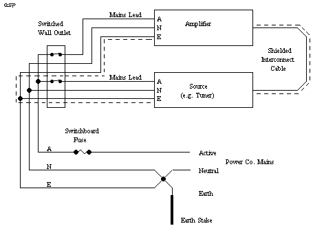
Figure 1 - The Formation
of an Earth Loop
Also note that the neutral (return) conductor is attached to earth at the main switchboard. This is standard in Australia and many other countries, but might not be the case where you live. Check with an electrician who can tell you how this is done (if you really want to know).
What happens if the amplifier develops an electrical fault that allows the live AC conductor to come into contact with the chassis? The current will flow from the chassis, through the earth connection, and the fuse will blow in the switchboard or in the equipment if a fuse is fitted.
Should the safety earth be disconnected from the power amp (for example), if a fault occurs in the amp, the only earth return is now via the interconnects (assuming that the source is earthed). These interconnects are not designed to withstand the fault current that can occur with a major electrical fault, and may disintegrate before the fuse. You now have a live chassis on the amplifier - just waiting for someone to touch it and die!
Residual Current Detectors
Many new installations use an "Earth Leakage"
or "Residual Current" detector, a device that will disconnect the AC supply
if the current flowing in the active (live) conductor is not exactly matched
by that in the neutral. Any imbalance means that current is going
somewhere it should not be, and the device will "trip".
These safety circuit breakers are very fast acting, and have saved many lives since their introduction. The 50mA that will kill you is detected by the breaker, and the power is disconnected - fast! Most of these type of breakers will operate on as little as 20mA, so you are not only protected against major faults, but also against excessive AC leakage caused by faulty insulation or moisture.
This does not mean that you can now go around disconnecting earth connections to stop hum - the safety devices that may be fitted to your house wiring are designed to trigger on a fault before you find it the hard way. In many countries, it is illegal to tamper with electrical (mains) wiring unless you are licensed - but in all countries, if it can be proven that you disconnected an earth that allowed a fault to kill someone else, you are liable, and may be subject to criminal charges ! Is that scary?
Main Earth Connection
For those who build amps (as is the case
with many of the readers of these pages), a common question is "How should
I connect the mains safety earth to the chassis?". As I stated above,
the regulations change from one country to the next, but the principles
are the same. Figure 2 shows a view of the basic connection, which
is very safe. The lug used must be an approved earth lug (or one
that meets any standards that exist where you live).
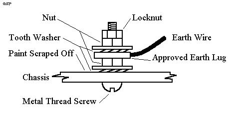
Figure 2 - Safe Method
Of Connecting The Safety Earth
Any paint (or anodising, in an aluminium chassis) must be scraped away to expose bare metal, and the tooth washer ensures that there is a good "bite" into the metal itself. The use of two nuts is strongly recommended, since the second one acts as a locknut, and prevents the first nut from loosening. The flat washers shown are optional, but highly recommended. They may be a requirement in some countries.
Do not use the earth connection as mounting for any other panel or component - it must be dedicated to the task of providing a safety earth point. If a component mounting bolt is used, at some stage it may be disconnected by a service (or other) person, which means that the apparatus is unsafe until everything is (hopefully) put back where it belongs - this does not always happen.
Make sure that the electrical connection between metal panels is also very well made. Some chassis are available in a kit form, and when screwed together, may not make good electrical contact with each other. Should the mains come in contact with a panel that has a "flaky" connection with the one that is earthed properly, the same potential for disaster is still present. All exposed metal must be properly and securely earthed.
The internal electronics of an amplifier should also be earthed, but now we have the problem of the hum loop again. There are two possibilities here.
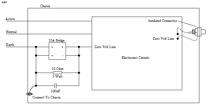
Figure 3 - A High Current
Safety Loop Breaker Circuit
I have simply shown all internal electronics as a box, with the only connection to the loop breaker being the zero Volt line. This is most commonly taken directly from the centre tap of the main amplifier filter capacitors, but should always be connected to a point where there is high current wiring back to the transformer. It is the transformer that provides isolation from the mains, and the possibility of an internal transformer fault must be catered for.
The only exception is if a double insulated mains transformer is used, but these are rare. Should the transformer be of "conventional" construction (not a toroidal), then the transformer body - the steel core - must be connected to chassis directly. Do not use any "loop breaker" circuit to isolate the transformer core, as it is unnecessary and dangerous to do so.
The loop breaker works by adding a resistance in the earth return circuit. This reduces loop currents to a very small value, and thus "breaks" the loop. The capacitor in parallel ensures that the electronics are connected to the chassis for radio frequency signals, and helps to prevent radio frequency interference. Finally, the diode bridge provides the path for fault currents. The use of a large chassis mounting (35A) type is suggested, since this will be able to handle the possibly very high fault currents that may occur without becoming open circuit. Note the way the bridge is wired, with the two AC terminals shorted, and the two DC terminals shorted. Other connection possibilities are dangerous, and must be avoided.
In the event of a major fault, one (or more) of the diodes in the bridge will possibly fail. Semiconductors (nearly) always fail as short circuit, and only become open circuited if the fault current continues and "blows" the interconnecting wires. High current bridge rectifiers have very solid conductors throughout, and open circuit diodes are very rare (I have never seen a high power bridge go open circuit - so far at least). Use of the bridge means that there are two diodes in parallel for fault current of either polarity, so the likelihood of failure (to protect) is very small indeed.
When a loop breaker is used, it is vitally important that all input and output connectors are insulated from the case. If not, they will instantly defeat the loop breaker by providing a direct connection from the zero Volt point to chassis, and no benefit is obtained. (Electricity has an annoying - but perfectly logical - tendency to travel along the path of least resistance, and a direct short circuit will always have less resistance than the loop breaker.)
It is not uncommon to have a voltage of
1 or 2 Volts between the earth connections of power outlets that are wired
separately back to the switchboard. This small voltage, with a total
resistance of perhaps 0.5 Ohm, will cause a loop current of 2 to 5 Amps,
all of which flows in the shield of the interconnect. This is sufficient
to cause a voltage difference across the interconnect, which the amplifier
cannot differentiate from the wanted signal. By breaking the loop
with the 10 Ohm resistor, the current is now less than 200mA, and the voltage
across the interconnect will be very much smaller, reducing the hum to
the point where it should no longer be audible.
| An earth loop will typically inject a 50Hz ot 60Hz hum into the signal - if you have a 100Hz or 120Hz hum (which often has a hard "edge" to the sound), you have done something wrong in the wiring of the power supply, and the technique above will not help. |
Mains Filters
In some cases, a transformer may be fitted
with an "electrostatic shield", which are lamentably uncommon in hi-fi
transformers. Where provided, these too must be connected directly
to the main earth point, and not via the loop breaker. Again, this
is unnecessary and potentially dangerous.
The purpose of the electrostatic shield is to intercept (and earth) any interference on the incoming mains. It does this by preventing any signal from being capacitively coupled from the primary to secondary windings, so the only form of coupling in the transformer is via the magnetic field in the transformer core. Most mains transformers have relatively poor high frequency response and this helps to further reduce interfering signals.
This can dramatically reduce extraneous noises (clicks, pops, whirring sounds, etc.) that might get into the system via the house and supply company wiring. This has great potential to pick up noise, since there may be 50 to 100km (or more) of cable involved between your amplifier and the generating plant.
In some cases, a mains filter might be fitted to amplifiers or other equipment (such as specially designed mains leads or "black boxes") to reduce any interference. Where fitted, if an earth connection is provided, it must be connected to the safety earth and chassis - never to the amp's zero volt line. Typical filters will use Metal Oxide Varistors (MOVs) to cut off any high voltage "spikes", and a capacitor and inductor network to filter out anything that is not at the mains frequency.
A true 50Hz (or 60Hz) tuned filter will be a large unit indeed, so most line filters only work at frequencies above a few kiloHertz. This is generally enough to get rid of most interference, since a well designed power supply should be able to filter out the majority of noise from the mains. Mains filters usually use the mains earth as a reference, so it must be present for the units to work correctly. Not using the safety earth as a reference is extremely dangerous, since the filters have capacitors which can (and do) become short circuited if a high voltage spike manages to get through and punctures the insulation.
Electrical safety cannot be over emphasised. Hum is damn annoying, and everyone wants it gone. There is no good reason to sacrifice one for the other, since safety and hum-free operation can peacefully co-exist with care and the right techniques.
As I have said several times, make sure that you find out the legal requirements in your country, and don't do anything that places you at risk - either from electrocution or legal liability. Neither is likely to be a pleasant experience.
Where the mains is noisy (apparently a common occurrence in the US), use of a dedicated mains filter is useful to prevent mains noise from entering the system. This will generally be unnecessary if the supply is well designed (especially if an electrostatic shield is used on the transformer), but this is often the exception, rather than the rule.
The use of "specialty" mains leads (unless fitted with a proper filter which will be in the form of a box in line with the cable) is unlikely to solve the problem - regardless of claims made by the manufacturers or reviewers (see "The Truth About Cables, Interconnects and Audio in General" for my comments on these - this article made a lot of audiophiles very unhappy, but advertising hype does not negate the laws of physics).