This project follows a project by Michael Dixon, which was based on an article in Electronics Today International in May 1992. This described a frequency division bat detector using a piezo detector, followed by an amplifier (LM381) and binary counter(CA 4040).
The circuit was found not to work, although it had some potential.
The system built by N. Wakefield uses the same outline
design, with the addition of a circuit to measure the amplitude
of the input signal, and control the output amplitude accordingly.
A final stage provides an audio amplifier to drive a loudspeaker.
Bats are fascinating creatures; they are able to fly in the same way that birds can but they do not have feathers, instead they have a fur coat. Bats are nocturnal and are able to navigate and catch their prey in complete darkness. Contrary to common belief bats are also very clean animals and groom themselves regularly. They only eat insects, and they rest and sleep upside down.
Scientifically bats are known as CHIROPETRA or HANDWING, because the wing is an evolution of the hand. When fully stretched it is possible to see the membrane extended between the four fingers, while the thumb protrudes from the front edge of the wing.
Bats cover a large amount of the Mammal kingdom, representing about a quarter of all the Mammals. In Britain alone they make up a third of the species of Mammals. Sadly the amount of bat population is on the decline due to the loss of the hedgerows and wooded areas that are their hunting ground. This is being lost to new building developments and new techniques in farming. The decline of insects is also a major factor as it is the bats main diet (in fact its only diet). A reduction in the number of bats is directly related to the amount of food available, as if there is no food then the bats will not be able to survive.
In Britain there are two types of Horseshoe bat and about a dozen types of ordinary bats.
In flight the bat avoids objects by using an echo location system, using short ultrasonic pulses that the bat emits in front of it. It then waits for the response that it picks up with its large ears, it listens to and interprets the echoes in the silence between the pulses.
This is the bat sonar, which allows the bat to navigate and manoeuvre onto its prey in complete darkness. The bat sonar is also very similar to the system used by dolphins. Their built in sonar produces bursts of ultrasonic waves which bounce back from objects, including insects, to give the bat a sound picture of their surroundings.
Until about 1940 nobody knew that bats used echo location. Scientists found it difficult to believe that bats could do anything remotely like the latest technological breakthroughs of electrical engineering, namely Sonar and Radar, which in 1940 were military secrets.
The extreme limits of the bat frequency extend from about 12kHz, which is just within the human hearing range, to 150kHz world-wide, although this does vary between species. As the frequency can be so low some overlap is going to occur with human hearing at the lower end of the scale. This sound will be like a high pitched crackling, it is not heard that often though and to most people bats are silent.
The constant frequency of the Lesser Horseshoe bat is about 110kHz, while that of the Greater Horseshoe is about 85kHz; both pulses last about 20 ms. Other bat sounds peak at about 80kHz and decrease in frequency from this peak. The characteristics of the sounds for a particular species, the number of pulses per second, their duration and pitch, can change depending on what the have been identified as Search, Approach, and Terminal activities. This is when the bat is flying around to locate its prey, it then homes in and then captures its meal. When it does this, a speeding up of the pulses occurs, the pulse rate increases, the frequency drops faster and the pulses get shorter.
Common bats will emit about 10 to 35 pulses per second in normal flight but the rate can increase to over 100 pulses per second at the home in stage of the attack. In the course of one pulse the frequency drops to half or even one third of its starting value, for example from 80kHz to 40kHz or 35kHz.
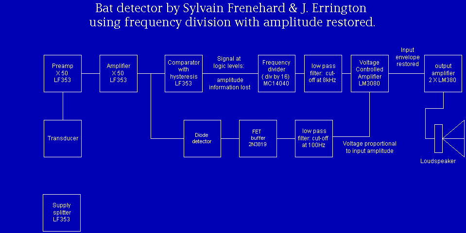
The full circuit diagram can be seen on figure 1. As you can see it is quite a large circuit so I have broken it up into smaller diagrams on the following pages, to make things simpler to follow.
The signal from the transducer is fed to a preamplifier,
following which its size is measured with an active detector circuit.
The signal is also fed to a second amplifier before being frequncy
divided by a binary counter IC. The reduced frequency square wave
is now filtered to remove high frequency components, and passes
through a gain controlled amplifier so that its amplitude is proportional
to the size of the input signals. Finally an audio output stage
allows the signal to drive a loudspeaker.
Block diagram of bat detector using frequency division with amplitude restored
The circuit is quite simple and is a combination of smaller circuits
brought together to make an effective detector powered by a PP3
battery. You will see that the LM381 chip has been used. The LM381
is a dual pre-amplifier for amplification with good low level
noise performance. The LM381 is epecially suitable for use in
this circuit, as it has a ain - bandwidth product of 15MHz, allowing
a stage gain of 200 at 75kHz. It is also designed for a single-ended
supply.
The ultrasonic sensor feeds the LM381 with the high frequency signal in the region of 20kHz to 200kHz. It would be possible to get a sensor that has a wide bandwidth and could detect any signal below or above that range, this unfortunately would be very expensive. Instead of using a wideband sensor I have decided to use a sensor that does not have such a big bandwidth, instead it has a small bandwidth but can detect in the region of 40kHz +1kHz. This is well above the human range and well into the bat range so it is able to pick up some bat emissions. The sensor is a piezoelectric material (usually ceramic) which provides small amplitude voltage variations when it receives a 40kHz signal. The sensor only picks a small portion of the bats bandwidth but it is enough to make the bat detector operable. Adding a resistor across the terminals of the transducer widens the bandwidth at the expense of reducing the sensitivity.
If you look at the circuit diagram you can see that a 470uF capacitor is across the supply terminals, this is to decouple any spurious signals in the circuit due to the high frequencies involved with the bat detector. A small 0.1uF capacitor is series with the sensor to pass AC signals from the sensor to the LM381. A de-coupling capacitor is across pins 9 and 4. The resistors and capacitors on pins 2, 7, and 13, 8 are used to set the gain of each stage.
I have mentioned the LM381 and its operation within the circuit, from here the circuit splits into two, from pin 7 on the 381 it branches off to the detector circuit (3130), and from pin 8 of the 381 it goes to pin 10 of the 4040 circuit.
The 4040 circuit is known as the frequency divider. It has a 0.1uF de-coupling capacitor across pins 8 and 16. Basically what this part of the circuit does is to lower the high frequency coming in from the sensor, to an audible version of the bat noise. The input, now a square wave, is divided by 16 so that a 48kHz signal will appear as a 3kHz output. It has single output, pin 5, that goes onto the 3080 circuit, which in turn goes onto the 380 circuit which are mentioned later in the report. In order for the 4040 to operate, it clocked by the second amp on the 381 chip. Having built these stages on bread board prototype I found them to work with some minor adjustments to resistor values. The 2.2uF capacitor on the power rail is there to stop spurious signals affecting the rest of the circuit. The schematic diagram of the 4040 chip is with the other technical data at the back of the report.
Back at the 381, pin 7 goes to a capacitor, diode , and resistor to the 3130 circuit. This part of the diagram is the detector circuit. A de-coupling capacitor is across pins 7 and 14. This amplifier operates for example if 0.5V is on pin 3 then the output on pin 6 after the diode but before the capacitor the voltage will be 2.5V. If a negative voltage is put onto pin 3 the circuit will not work. This is because the diode will not conduct.
The 3080 circuit is an envelope shaper, I discovered this in the Maplin catalogue (pg. 792). The 3080 circuit is connected from the output of the 4040 circuit pin 5. You can see that pin 3 is connected via two resistors and two capacitors that are connected to a floating point. Pin 2 is also connected to the same floating point via a resistor, from this point they are connected to ground via a resistor and capacitor.
A de-coupling capacitor value of 0.1uF is connected across the input pins 7 and 4. Pin 4 is connected to ground via two diodes IN4148 the same type as that in the 3130 circuit, this type of diode is used for audio frequency circuits such as this one and fit rather well into the circuit. The diodes from pin 4 do not serve much purpose but the circuit works with them in so if it isn't broken then don't fix it. Pin 5 is connected to the output of the 3130, pin 5 is the amplifier bias input, which is used in linear gate control. The 3080 is a operational transconductance amplifier (ota) and is gateable-gain block. The technical data about this IC is held at the back of this report along with the other data sheets. The 3080 is used in the circuit for its ability to mirror the current as below.
Finally we come to the 380 circuit. the technical data of which can be found at the back of this report with the others. This provides a large enough signal to drive the loudspeaker. A 100k potentiometer is placed between pins 2 and 6, this acts as a volume control. The schematic diagram is shown in the technical data. It is easy to use on a PC layout as the chip is mounted on a copper lead frame, which connects directly to the copper of the PCB, which is used as a heat sink. This circuit is also de-coupled across pins 7 and 14 with a 220uF capacitor. From pin 8 there is a 2.7 ohm resistor and 0.1uF capacitor, making up a Zobel network. A 47uF capacitor connects to the speaker. Finally to complete the circuit, 3 high intensity LED's have been added, to provide an emergency light source.
Having built all the different stages and found them all working after changes to the values of some of the resistors, and working out any of the bugs still left in the system, and after de-coupling all the IC's it is necessary to give the circuit a more permanent home.
To do this the ultimate aim is to build it onto a PCB. Using Cadstar I was able to design the circuit as shown on the diagram overleaf. The idea is to build the circuit onto a smaller size board as possible. This is quite difficult because of the high frequencies that each of the IC's has to deal with, so in order to cut down on any spurious signals the chips make, affecting each other, the board must be laid out as the following diagram represents.
As you can see it is more or less the opposite way around from the circuit diagram. The 380 chip has most of the signals that are likely to effect the other parts of the circuit, this is the reason for the 380 chip being separated as far as possible from the other IC's on the PCB diagram shown over. The board is 156mm long and 94mm wide, making it a large board to deal with but the circuit being built makes this a necessity.
Although I had planned to keep all the tracks on one side, it became increasingly difficult as the number of tracks multiplied, so in the end I was forced to use both sides of the board. When using Cadstar it is necessary to know the sizes of each component, unfortunately I did not take into account the size of the casing and only measured the distance between the pins, this was all right in terms of resistors because they are all the same but when it comes to capacitors, some of the casing is very much larger. Having realised this I then had to return to the PCB and move components until there was enough space between them to be placed on the board comfortably.
Another set back that I became aware of is when using double layers. I discovered that it is not possible to run a track on the top of the board from one IC to another. This is because when it comes to soldering it is not possible to solder the pins on the tracks of the top layer due to the fact there is not enough space to get the soldering iron in around the leg of the chip. To overcome this a track must be taken from the bottom layer to a through hole, away from the chip, then a track can go along the top layer to it's destination, if this destination is another IC then it will be necessary to go a through hole again to get to the bottom layer and on to the chip. I would like to express that this sort of manoeuvring around the board should be kept to a minimum to avoid extra resistance's that may occur.
When connecting pins on the IC's care must be taken that mistakes are not made as those shown below.
I mention this because when designing a PCB a lot of points on the circuit are the same, were there are several components that have the same power supply and the same ground, but if they are connected incorrectly as shown in the diagram above then the circuit will be affected and most probably be rendered useless.
An example of this from the PCB is the fact that pin 7 is ground on the 380 circuit and theoretically could be connected to the ground of any other IC, unfortunately this is not the case because of the high frequencies associated with the 380. It is more effective if the ground is kept separate in this case, it does not necessarily mean that all ground planes be kept apart on the contrary many of the points on the board that are connected to ground take a shorter route via a different component.
Finally in order to screen the PCB from any outside noise, which is highly likely due to the sensitivity of the circuit, ground planes have been placed around the input transducer. Not only have I put them around the transducer, if you look at the PCB circuit you will see that the ground rail goes nearly all the way around the board, in order to reduce any noise. Not only have I taken these precautions I have made the tracks of the +ve and -ve rail as large as possible, the other tracks have made to be one size less than those, this will help the large signals.
In order for the detector to be carried/transported it should be fitted into a box, which should have a battery compartment. The box I have chosen to use is in the Maplin catalogue. The on/off switch and LEDs and volume control will all be fitted to the box, along with the sensor.
During construction some minor errors were discovered in the PCB. More importantly the circuit was found to be unstable, particularly the LM380 audio amplifier, which oscillated at about 2MHz. It was also found that the LM381, although an excellent choice for the input amplifier, was not entirely suitable as a comparator. This resulted in the output frequency from the counter increasing as the input amplitude was increased, due to distortion in these early stages.
It was also found that the benefit of a frequency division technique, in being able to cover the whole of the bat spectrum without tuning, was not being realized owing to the very narrow bandwidth of the detector. It was possible to extend this bandwidth by adding a parallel load resistor of about 600 ohms across the detector, but this greatly reduced the sensitivity.
This will involve a search for a better transducer; the use of a FD circuit using a dual stage preamplifier (LM381) followed by a noise rejection circuit and comparator. The active detector and OTA gain controlled amplifier will be retained, on an improved PCB, with a ground plane to prevent oscillation and pick-up which have proved to be important in this design.