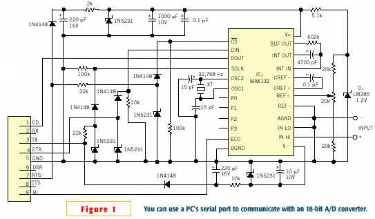
| Serial Port Driven, 16-bit A/D Converter Here is a high resolution A/D converter from EDN Magazine that can be driven from a ubiquitous, 9-pin serial port. Edited by Bill Travis A PC usually requires a plug-in ADC card to process analog signals. However, with the circuitry in Figure 1, a PC can communicate with an 18-bit ADC through its serial port. The port provides both positive and negative power supplies as well as control signals. IC1 is an 18-bit MAX132 ADC with a serial interface. It requires three input control signals, , DIN, and SCLK, and emits serial data, DOUT, and EOC (end-of-conversion) signals. An RS-232 port has three output lines: Pin 3 (TX), Pin 4 (DTR), and Pin 7 (RTS). TX generates the clock signal for the MAX132 and provides the negative power supply. DTR transmits serial data. RTS provides the CS signal and the positive power supply. Both the positive and the negative supplies use large capacitors for energy storage. When TX generates a clock signal or DTR sends a CS logic-low signal, the capacitors provide power to the MAX132. The MAX132 integrates everything except a reference that comes from a 1.2V LM385 voltage-reference diode, D1. The input-voltage range of the MAX132 is -512 to +512 mV. Listing 1 is a C program that displays the analog-to-digital-conversion result on-screen.
|
