This circuit is a simple 8-bit analogue to digital converter circuit which is connectes to PC serial port. The circuit is based on TLC548 A/D-converter chip, which is an A/D-converter with serial output. The output of the TLC548 is not directly suitable for standard serial data reception, so this circuit uses serial port handshaking lines in a nonstandard way which enables the communication between computer and converter chip to be implemented with as few components as possible. The circuit takes all the power it needs from PC serial port.
Maximum sample rate: 40 000 sampes/second (maximum rate of TLC548 chip)
Input voltage range: 0-5 V
Accuracy of A/D converter chip: 8 databits (+-0.5 LSB)
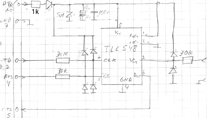
The picture below is tha circuit diagram of the circuit. The pin numbers of the connector are pin numbers of 25-pin serial port connector. All diodes are IN4148 or similar. All resistors connected to IC are 30 kOhm and their function is to protect the IC inputs with the diodes against overvoltages. The 1 kOhm resistor, one diode, 5.1V zener-diode, 10uF and 100nF capacitors make the power supply which takes circuit power from serial port Data Terminal Ready -pin.
Circuit diagram of the serial port A/D converter. This picture is available separately in GIF format.
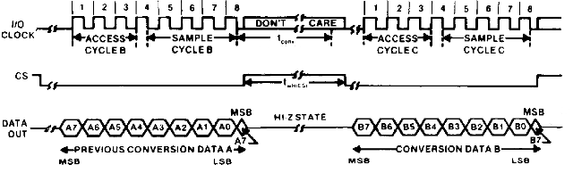
The following signal diagram tells that signals are needed for controlling the TLC548 A/D conversion chip. The chip needs chip selected (CS) and i/o clock signal (CLK) to operate. The chip gives the conversion results from data output pins (Dout). Those signals are simple and easy to understand and can be easily generated using simple software routine.
Signal diagram of TLC548 chip. This picture is available separately in GIF format.
This type of signalling is quite common in many A/D converters with serial outputs. There are differences in different type of A/D conveters, but you can easily use the ideas used in this circuit for interfacing other types of A/D conveters to your PC.
Here is a simple program for testing and operating A/D converter circuit. The program is written using Turbo Pascal version 4.0 and can be compiled with never versions also. This program needs to know the address of your PC's COM-port and you have to set it to the source code before running it. If you have very fast computer, you might have to add some delay after if I/O access.
Program serial_adc;

Uses Crt;

Const
    combase=$2f8;    { I/O address of the COM port you are using }
    MCR=combase+4;
    LCR=combase+3;
    MSR=combase+6;

Procedure Initialize_converter;
Begin
   Port[MCR]:=3;
   Port[LCR]:=0;
End;

Function Read_value:byte;
Var
   value:byte;
   count:byte;
Begin
   value:=0;
   Port[MCR]:=1;
   For count:=0 to 7 Do Begin
      value:=value SHL 1;
      Port[LCR]:=64;
      If (port[MSR] and $10)=$10 Then Inc(value);
      Port[LCR]:=0;
   End;
   Port[MCR]:=3;
   Read_value:=value;
End;

Begin
   Initialize_converter;
   Repeat
      Writeln(Read_value);
   Until KeyPressed;
End.
Tomi Engdahl <then@delta.hut.fi>