|
MODULE 6-10 POLARIZERS © Copyright 1988 by The Center for Occupational Research and Development All rights reserved. No part of this book may be reproduced in any form or by any means without permission in writing from the publisher. The Center for Occupational Research and Development Printed in the U.S.A. ISBN 1-55502-024-0 (1) Unpolarized light consists of wave vibrations in many directions perpendicular to the direction of travel. A polarizer is a device that filters out or blocks all vibrations, except those desired, which in the ideal case may be only a single vibration. This vibration is transverse to the direction of travel of the beam. (2) A polarizer is only a selector. It doesn’t create transverse vibrations but rather preferentially selects certain transverse vibrations and rejects others. This selection is accomplished using one or more of the principles of absorption, reflection, and refraction. This module will acquaint you with the types of polarizers, how they work, and how to use them. (3) To better understand this module, you should understand the theory of polarized light. (4) When you complete this module, you should be able to do the following:
DISCUSSION (5) Light is a form of wave motion, but it travels so fast (186,326 miles per second) that we can’t see the ways in which the moving waves vibrate. This wave motion must be known to describe the operation of polarizers. So, first we’ll discuss some important features of light waves. (6) Even though we can’t see light waves, experiments have shown that the electric and magnetic fields in light waves vibrate at right angles to the direction of travel of the beam. Light therefore is said to consist of transverse waves. For example, if the direction of travel of a given light beam is east, the electric vibrations may be up and down, or north and south, or along any other line perpendicular to the east-west axis. (7) Figure 1 shows a "snapshot" of a plane-polarized wave traveling from left to right, made up of transverse electric (E-vector) and magnetic (B-vector) components. Fig. 1 (8) The plane containing the E-vector and the direction of propagation is called "the plane of polarization," which in Figure 1 is shown as the vertical plane. In polarization work, the direction of the E-vector is specified, so only the electric component will be shown and considered during the remainder of this module. In the plane-polarized transverse wave it’s necessary to specify two directions, that of the wave disturbance (the E-vector) and that of propagation. In plane-polarized transverse waves, we can thus expect a lack of symmetry about the axis of propagation. This lack of symmetry in the limit is polarization, but let’s establish that definition more clearly. (9) Electromagnetic waves in the radio and microwave range readily exhibit this lack of symmetry. Such a wave, generated by the swinging of charge up and down in the dipole that forms the transmitting antenna, has an electric field vector parallel to the dipole axis. This is shown in Figure 2. Fig. 2 (10) When this plane-polarized wave falls on a second dipole connected to a microwave detector, the alternating electric component of the wave will cause electrons to surge back and forth in the receiving antenna, producing an indication on the detector. If we turn the receiving antenna through 90° about the direction of propagation, the detector reading drops to nearly zero. In this orientation the electric field vector can’t cause charge to move along the dipole axis because it points at right angles to this axis. (11) Most sources of visible light differ from the microwave source shown above in that the elementary radiators—that is, the atoms and molecules—all act independently. The light propagated in a given direction consists of independent wavetrains whose planes of vibration are randomly oriented about the direction of propagation. This situation is shown in Figure 3 looking along the direction of propagation (into the paper). Fig. 3 (12) Such light, though still transverse, is unpolarized. A prime purpose of polarizers is to sort out different planes of vibration of such radiation. Polarized light is light whose transverse vibration has a simple pattern. Figure 4 shows a light wave traveling along the Z-axis of a right-handed coordinate system. The electric vibrations are horizontal, and accordingly the light is said to be polarized linearly and horizontally. Fig. 4 (13) The right portion of Figure 4 shows the sectional end-on pattern, which corresponds to a time-exposure photograph taken by a camera looking at a cross section of the beam. The camera is situated on the axis of the beam and aimed straight at the light source. When the transverse vibrations are vertical, the cross-sectional pattern is indicated by a vertical line, and the light is said to be polarized linearly and vertically. This case is shown in Figure 5. Fig. 5 (14) Don’t infer from the figure that that light "wiggles" side to side. Rather the pattern should be interpreted as a plot of the electric field strength within the light wave as a function of distance (or time). (15) With the proper phase relationship between vertically and horizontally polarized beams, the snapshot pattern is a helix and the sectional pattern is a circle. This case is shown in Figure 6. Fig. 6 (16) By the most common convention, if the light is viewed looking toward the source and the electric field rotates clockwise, the polarization is called "right-hand circular." Similarly, a counterclockwise rotation would be called "left-hand circular polarization." (17) Figure 7 shows how two plane-polarized waves of equal amplitude and at right angles to each other can create circularly polarized light. The two waves of Figure 7 differ in phase by 90°. Where one wave has maximum values, the other is zero. Values of the resultant amplitude of the approaching wave for positions 1 through 8 as seen by an observer looking toward the oncoming wave, are indicated in the small squares under the wave pattern. Note that an observer looking toward the approaching wave will see the resultant vector rotate counterclockwise with time and form left-hand circularly polarized light. Fig. 7 (18) In a similar manner, if the amplitudes of the horizontal and vertical electric field components are not equal, so called elliptically polarized light can be produced. As an alternative, the phase difference between the components can be changed to produce elliptical polarization. You can find complete discussion of such effects in most introductory physics texts under the topic of Lissajous figures. (19) Polarizers are devices that change light from the unpolarized state of Figure 3 to one or more of the states shown by Figures 4, 5, and 6. The remainder of this module will be concerned with how polarizers operate and how they are used.
Types of Polarizers (20) In the laboratory the usual method of producing polarized light is the common, three-step method of first producing ordinary unpolarized light, then reducing this to two orthogonally polarized components, and finally eliminating one of these components. The component that remains is polarized light. This process is inefficient, but inexpensive and simple. (21) A polarizer is really a divider-and-selector. It doesn’t create transverse vibrations. It merely divides all existing vibrations into two classes. There are many types of polarizers. That’s because so many types of optical manipulations can be used. The processes of absorption, reflection, refraction, and scattering can be used to resolve a beam into polarized components.
Dichroic Polarizers (22) Dichroic materials have the property of selectively absorbing one of the two orthogonal components of ordinary light. Dichroism is exhibited by a number of minerals and by some organic compounds. (23) Dichroism was discovered early in the nineteenth century. And one of the crystals exhibiting it, tourmaline, was a commonly used polarizer for some time. Although this particular crystal has many shortcomings, the same principle of dichroism has been used to produce perhaps the most frequently used polarizer, namely Polaroid type-H sheets. (24) The simplest analogy to a dichroic polarizer is given by the wire grid as shown in Figure 8. We can explain the dichroic polarizer theory simply in terms of this device. The wire-grid polarizer consists of an array of slender wires arranged parallel to one another. The metal wires provide high conductivity for electric fields parallel to the wires. Such fields produce electric currents in the wires, like the microwave dipole receiver antenna. The energy of the fields is converted to energy of currents in the wires. This current then is converted to heat because of the small but significant electrical resistance of the wires. Fig. 8 (25) Because of the nonconducting spaces between the wires, no current can flow perpendicular to them. So electric fields perpendicular to the wires produce virtually no currents and lose little energy. The wire grid, when placed in an unpolarized beam, drains the energy out of one component and lets the other component pass with almost no attenuation at all. The transmitted component is the one whose electric field vibrates in a direction perpendicular to the wires. (26) An example of light passing through a dichroic material is shown in Figure 9. The randomly polarized light entering T1 is reduced to simple vertical polarization, which passes unaffected through T2 when its orientation is the same as T1. If T2 is rotated 90° it has the effect of two wire-grid polarizers at right angles to each other, and virtually no light passes. (27) Although the wire-grid polarizer is easy to understand, it’s too difficult to make to be practical. The wires have to be on the order of a wavelength of light apart, and this is difficult and very expensive. Fig. 9 (28) A better way had to be found. This happened in 1938 when E. H. Land invented H-Polaroid sheet. Think of the H-Polaroid sheet as a chemical version of the wire grid. Instead of long thin wires it uses long thin polyvinyl alcohol molecules that contain many iodine atoms. These long, straight molecules are aligned almost perfectly parallel to one another and about 3 Å apart. Because of the conductivity provided by the iodine atoms, the electric vibration component parallel to the molecules is absorbed. The component perpendicular to the molecules passes on through with little absorption. (29) The way Land produced this type of polarizer is shown in Figure 10. A sheet of polyvinyl alcohol was heated and then quickly stretched to many times its length. During the stretching operation most of the long polymer molecules were turned so as to have nearly the same direction, namely, the direction of the stretching force. Fig. 10 (30) The next step was to dip this stretched sheet into a liquid solution that was rich in iodine. The iodine atoms diffused into the polyvinyl-alcohol layer and attached themselves to the thin, nearly parallel molecules. So the iodine atoms imitated their host and formed long thin chains. (31) These iodine chains in Polaroid act like wires. They absorb electric field vibrations parallel to their aligned axis and transmit freely the vibrations perpendicular to that axis. So the transmission axis is perpendicular to the stretched direction. (32) Figure 11 shows the effect of Polaroid material on light when two sheets are lined up parallel and when two are used perpendicular to each other. Fig. 11 (33) Many other kinds of dichroic sheet polarizers can be made. Some use dyes that consist of long thin molecules, and some use long thin crystals. However, all of these types are similar in theory to the Polaroid sheet mentioned above.
TM and TE Polarizations (34) Before we continue our discussion of the methods of polarizing light, it’s helpful to define two particularly important polarizations, TM (transverse magnetic) and TE (transverse electric). These two orthogonal (mutually perpendicular) polarizations are shown in Figure 12. Note that the short arrows (TM polarization) in Figure 12a represent an electric field vibrating in the plane of the page, perpendicular to the beam direction. The dots (TE polarization) in Figure 12b represent an electric field vibrating in and out, perpendicular to the plane of the page. These vibrations are also perpendicular to the beam direction. Fig. 12 (35) TM and TE are defined with respect to the so-called "plane of incidence" (POI) which is the plane containing the normal to the surface and the incident ray. So in Figure 12, the POI is the plane of the page. Note that in Figure 12a the electric field is in the POI. This means that the magnetic field must be transverse (across or perpendicular) to the POI. On the other hand, Figure 12b shows the TE polarization with the electric field transverse (perpendicular) to the POI. In both figures for the TM and TE polarizations, only the electric field is shown to avoid confusion.
Reflection-type Polarizers (36) Perhaps the simplest method of polarizing light is the one discovered by Malus in 1808. If a beam of unpolarized white light is incident at one certain angle on the polished surface of a plate of ordinary glass, it is found upon reflection to be linearly polarized. (37) When the glass plate is oriented so as to be perpendicular to the beam (making a zero angle with the normal) no polarization of the light results. All vibration components of the light are transmitted equally and the transmitted beam is found to be unpolarized. About 8% is reflected, (4% at the top surface) and the reflected light is also unpolarized. (38) When the incident ray is tilted so as to make some angle q with the normal, the symmetry of the reflection process is destroyed, and the transmitted and reflected beans are found to be partially polarized. This situation is shown in Figure 13a. Fig. 13 (39) When the angle of incidence is further increased to a so-called Brewster angle qB, TM polarization is 100% transmitted, which leaves the reflected beam as pure TE polarization, as shown in Figure 13b. Note however, that part of the TE polarization is still present in the transmitted beam but none of the TM polarization is present in the reflected portion of the incident beam. You can find Brewster’s angle from the expression
For example, for a glass plate (n2 = 1.52) in air (n2 = 1.00), Equation 1 gives
If you have studied Introduction to Lasers, you will recall that this is the angle at which a laser Brewster window is oriented on the end of a plasma tube. This is common, for example, in most argon or krypton ion lasers. (40) Sometimes reflection plate polarizers are composed of several plates and are called "stacked plate" or "Brewster stack" polarizers. Using many plates further increases the purity of the transmitted polarization by removing more and more of the TE polarization. Brewster stacks are generally of two types—linear stacks or tent stacks. The latter has the advantage of producing an undisplaced beam. (See Figure 14.) Fig. 14 (41) Polarizers of the reflection type have several attractive features. They can be designed for use in any part of the spectrum. Also, they are easy to make and can have very high thresholds for laser-induced damage. On the other hand, reflection-type polarizers seldom are used to polarize light in the visible range because they are outperformed by the sheet polarizers discussed previously. Only in certain parts of the infrared and ultraviolet range are reflection-type polarizers superior, or in high-power laser applications where other types of polarizers would suffer laser-induced damage. (42) Other types of polarizers based upon reflection (and transmission) also are becoming important for high peak power laser applications. These polarizers generally are constructed in the form of thin dielectric coatings. So they are called "thin-film polarizers." There are two principal types. (43) The first thin-film polarizer, called a MacNielle biprism polarizer, uses a thin-film multilayer dielectric between two prisms. The second is more generally used because of its reduced cost and capability for larger size. It’s the thin-film multilayer stack placed on a suitable substitute. This combination then is placed at an appropriate angle in the beam. (44) Simply stated, these polarizers, similar in many ways to thin-film filters, exhibit vast differences in reflection and transmission characteristics for the two types of polarization, TM and TE, at a specific selected wavelength. The ratio between the transmission of TM and TE polarization—sometimes called an "extinction ratio"—can reach several hundred or even a thousand. (45) Increased discrimination can be achieved by using several plates in combination. However, these thin-film polarizers are fairly sensitive to angular orientation. For a further description of these novel polarizers, see the referenced article by Austin.
Double-refraction Polarizers (46) Polarization was discovered with the aid of crystals that exhibit double refraction. It was discovered by the Dutch scientist Huygens while he studied some crystals of the doubly refracting mineral calcite (CaCO3). Double refraction is a complicated subject that requires an understanding of crystallography. Because the crystal structure is so complicated, we won’t explain the reasons for the double refraction. Rather we’ll concentrate on the effect of calcite on the light beam. (47) If a polished crystal of calcite is laid over a black dot, the image of the dot appears double. This double bending of a beam through calcite is called double refraction. Figure 15 shows a beam of unpolarized light falling on a calcite crystal. The direction of symmetry through the crystal—known as the optic axis—runs diagonally along the crystal, from A to B. With the optic axis in this direction, the single beam splits into two at the crystal surface. Fig. 15 (48) If you do experiments at various angles of incidence, you will find that one of the beams of Figure 15 obeys Snell’s law of refraction at the crystal surface, just like any ray passing from one medium to another. This beam is represented by the "ordinary" or O-ray in Figure 15. (49) The other refracted beam does not obey the laws of refraction. This beam is called the "extraordinary" or E-ray. You can understand the difference between the waves represented by the O- and E-rays with respect to the laws of refraction in these terms:
(50) It should be clear that constructing a polarizer out of calcite is easy. In fact any smooth-faced calcite crystal is already a polarizer. The natural crystal structure of double-refracting crystals causes them to polarize light. When inside the crystal, light travels in slightly different directions, depending on its polarization. The polarizations emerge at slightly different places. So they constitute two side-by-side beams of linearly polarized light with mutually perpendicular vibration directions. But unless the incident beam is very slender or the crystal is very large, the two emerging beams will overlap a good deal. Several geometries have been formed with calcite that overcome this problem.
The Glan-Foucault Polarizer (51) One design of a calcite polarizer is that invented by Glan and Foucault. It’s shown in Figure 16. Two right-triangular pieces of calcite are used. The two pieces are mounted side by side and held so that there’s a thin air gap between the respective hypotenuses as shown in Figure 16. Fig. 16 (52) When a beam of unpolarized light strikes one prism along the normal to the end face, it enters the prism and forms two beams there, namely the O-ray and the E-ray. The inventors chose an angle for the hypotenuse so that one beam is totally internally reflected and the other is transmitted. This is shown in Figure 17. Fig. 17 (53) The reflected beam strikes some black paint on the side of the first prism and is absorbed. The transmitted beam proceeds onward, into the air gap, and through the second prism. The degree of polarization of this beam is practically 100%. (54) Since calcite is transparent from the ultraviolet (230 nm) to the infrared (5000 nm), and since the Glan-type polarizer contains nothing but calcite, this polarizer can be used throughout a large spectral range. One drawback however, is that the incident beam must strike the entrance face no more than 7° off normal.
The Glan-Thompson Polarizer (55) If the two prisms of the Glan-Foucault polarizer are cemented together and the air gap is eliminated, the device is called a Glan-Thompson polarizer. It has an advantage over the Glan-Poucault polarizer in that it can accept incident light far in excess of 7°. One drawback of this type is that the cement used is normally opaque to certain wavelengths and subject to damage at high light intensities.
The Nicol Polarizer (56) Another useful polarizing device made from calcite is the Nicol polarizer. The Nicol polarizer, like the Glan polarizers, removes one of the refracted rays by total reflection inside the polarizer. As shown in Figure 18, the Nicol polarizer also is made of two triangular wedges of calcite. In this case however, the wedges are cemented together with Canada balsam which has an index of refraction about midway between the index of the O- and E-rays. The angle over which incident light can enter a Nicol polarizer and successfully pass through is about 14°. Fig. 18 (57) The Nicol polarizer performs well. But it has a limited spectral range because of the absorption of ultraviolet light by the Canada balsam.
Rochon Cubic Beamsplitter and Wollaston Polarizers (58) The double-refraction type of polarizers mentioned above are designed to transmit one of the beams and absorb the other. Sometimes you need a polarizing device that transmits both beams and separates them widely enough so that each beam can be used independently. This device then serves as both a polarizer and a polarizing beam splitter. This is true for the Rochon prism shown in Figure 19a.
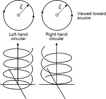
Fig. 19 (59) In the first half of the Rochon prism, both the ordinary and the extraordinary rays travel with the same velocity. In the second half, the ordinary ray continues at the same velocity. But the extraordinary ray travels more rapidly and therefore is deviated by an amount that depends on the angle of the interface. (59a) The cube beamsplitter shown in Figure 19b achieves a 90° separation of the polarized beams, a larger separation than with the Rochon prism. Cubic beamsplitters are made by cementing two precision right-angle prisms together. Before cementing, a metal-dielectric film is vacuum deposited on one of the hypotenuse faces. This beamsplitter, available in cubes from 5 mm to 50 mm on edge, is mechanically strong and free of ghost images. Single-layer Mg F2 antireflection coatings are applied to the entrance and exit faces of the BK-7 prism material. (60) The Wollaston polarizer shown in Figure 20 behaves similarly. But it deviates the beams in opposite directions. The ordinary ray in the first half of the prism becomes the extraordinary ray in the second half, and vice versa. So one ray is deviated by the same amount that a Rochon prism would deviate the extraordinary ray, and the other is deviated by very nearly the same amount. Fig. 20 (61) The Rochon prism is used in optical instruments to produce a plane-polarized beam. The O-beam is used and the E-beam is screened off at a sufficiently large distance from the prism. (62)The Wollaston prism is used where a comparison of intensities is desired. So both beams are used. The intensities of the two output beams will be equal if the input beam is unpolarized, but they will differ if the input beam is polarized to any measurable extent.
Retarders-Polarization Converters (Wave Plates) (63) Retarders are not polarizers in the strict sense of the word. They have no effect on unpolarized light. But they’re very useful in changing the orientation or form of polarized light. In common usage, the words"retarder" and "wave plates" have come to refer to the same device. (64) The principle of operation of a retarder or wave plate is easily stated. It divides an incident, polarized beam into two components, changes the phase of one relative to the other while passing through the wave plate and then recombines them as they leave the wave plate. Because of the resulting phase shift, the exit light has a different polarization form. Since the key step is the introduction of a relative phase shift, some people call the device a "phase shifter," a "wave plate," or a "retarder." (65) A typical retarder consists
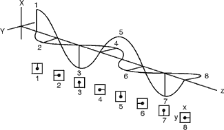
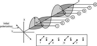
of a thin crystalline plate as shown in Figure 21. Let’s assume
that a linearly polarized beam is incident on the plate from the left
as shown. You can consider the incident
beam to have a vertical vibration and a horizontal vibration Fig. 21 (66) We’re interested only in relative retardation. In calcite the beam with the vertical vibration direction is slowed. This vertical direction is called the "slow axis." The direction of vibration of the faster-traveling beam is conversely called the "fast axis." (67) The thickness of the wave plate and so the time the light spends inside the crystal determines the amount of phase shift. If the phase shift is 90°, the retarder is a quarter-wave plate. It can convert linearly polarized light into circularly polarized light, and vice versa. A half-wave plate rotates the incident plane of polarization through an angle 2q, where q is the angle the vibration direction of the incident polarized light makes with the direction of the optic axis in the crystal face. Figure 22 shows the effects of a quarter-wave plate and a half-wave plate. (68) In Figure 22a, linearly polarized light, oriented at 45° to the direction of the crystalline optic axis, is treated as an x-conponent and a y-component, each equal to the other. Upon entering the birefringent crystal, the y-component, aligned with the fast axis, travels through the crystal faster than does the x-component, which is aligned with the slow axis. The two components are thrown 90° out of phase with each other, such that upon emerging, one is always maximum while the other is always zero and vice versa. (See Figure 22b) The effect is to produce circularly polarized light, as seen by an observer looking into the crystal. The 90° phase shift is produced by a precise thickness d of the birefringent crystal, which, because of the 90° shift, is referred to as a quarter wave or l/4 plate.
(a) Quarter-wave plate converts linearly polarized light to circularly polarized light.
(b) Development of circularly polarized light by a quarter wave plate.
(c) Half-wave plate rotates linearly polarized light by angle 2q about the crystal's optic axis. Fig.
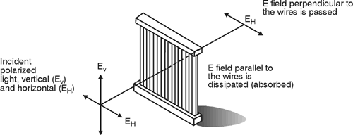
22 (69) Figure 22c shows how a half-wave (l/2) plate rotates linearly polarized light, initally oriented at some angle q to the optic axis direction in the crystal, through an angle 2q. The emerging linearly polarized light thus shows up at an angle q on the opposite side of the crystal's optic axis direction. (69a) Note that the actual thickness of the l/4 or l/2 plate is NOT equal to l/4 or l/2. (That would indeed be a THIN plate!) The symbol l/4 or l/2 simply refers to the crystal's effect of separating the two components—FAST and SLOW— by 90° (l/4) or 180° (l/2). The actual thickness of the wave plate—either a l/4 or a l/2 plate—depends on the phase shift desired, the vacuum wavelength of the incident light, and the two indices of refraction of the wave components traveling along the fast axis and slow axis of the crystal.
Uses of Polarizers (70) Polarizers are used in our everyday lives as well as in the optics laboratory. We’ll give some examples of popular uses. (71) Polarizing sunglasses take advantage of the fact that in nature "glare" consists mainly of light-having a horizontal vibration direction. The reason for this is that sunlight comes downward and hits mostly horizontal surfaces (such as the oceans). Reflection from such a surface results in polarization with a predominant horizontal vibration. (See Figure 13a.) Figure 23 shows that in polarizing sunglasses the transmission axis is vertical and thus reduces the glare reflected from horizontal surfaces. Fig. 23 (72) Solutions of various sugars and other organic substances have the property of rotating the plane of polarization of light that passes through them. The extent of this rotation is measured with a polarimeter. As shown in Figure 24, this instrument is comprised of a source of light (usually a sodium lamp), a polarizer, a tube to hold the sample and an analyzer. An analyzer is simply another polarizer that can be rotated. Fig. 24 (73) To use the device, the tube is first filled with water, the lamp turned on, and the analyzer rotated until no light is seen to emerge from it. The polarizer and analyzer then are said to be "crossed." The water in the tube then is replaced by the solution under test. The analyzer again is rotated until it’s again crossed with the polarizer. The change in the plane of polarization is thus determined. Such information provides clues to the structure of these compounds. The amount and direction of polarization indicate the strength, concentration, and type of the solution. (74) A further example of the use of polarization is the Kerr cell that was used in high-speed photography and in modulating beams of light. This cell depends on polarization effects induced in a liquid as shown in Figure 25. Fig. 25 (75) Light is vertically polarized by the first polarizer and, unless it is changed by 90° in the retarder, it can’t pass through the second, horizontally-oriented polarizer. This arrangement forms a shutter that can open and close in 10–12 seconds. A similar effect occurs in some solid materials and is called the "Pockels effect." Pockels cells are used, for example, as laser Q-switches and have all but replaced the more cumbersome Kerr cells.
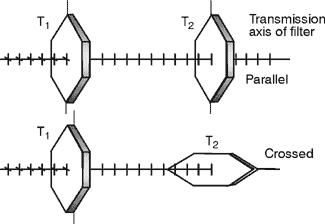
The Law of Malus (76) The irradiance of plane polarized light passing through a polarizer is given by the so-called "law of Malus,"
Note: In many references to the Law of Malus, intensity I is used instead of irradiance E. In keeping with our adoption of E as the irradiance, measured in units of power/area, Equation 2 is given in terms of E. Fig. 26 (76a) In Figure 26, note that the incident linearly polarized electric field vector, of amplitude Ao, is vibrating at an angle f with the x-axis. The component of Ao along the x-axis is Ao cos f. It is this component only which gets through the polarizing filter, whose transmission axis is horizontal, that is, parallel to the x-axis. Since the irradiance is equal to the square of the amplitude, the incident light has irradiance Eo equal to Ao2, and the emerging light has irradiance E equal to Ao2 cos2 f, or E = Eo cos2 f, the law of Malus. (77) For example, if the maximum transmission of a polarizing filter is 90% and its horizontal transmission axis is oriented at 30° to the plane of the incident light’s polarization, then, using Equation 2, E = 0.90 Eo cos2 30° = 0.675 Eo Since T = E/Eo = 0.675, the transmission of the filter is 67.5%. (78) Note that, if the area of the beam is unchanged as it passes through the filter, Equation 2 can be written as,
where P and Po are in power units rather than irradiance. (79) Furthermore, you can compute the transmission of a series of linear polarizers by successive application of the Law of Malus. More complicated combinations of polarizing filters (quarter-wave plates, half-wave plates, and so on) can be handled easily by the Jones vector theory, a powerful matrix technique explained in many optics texts.
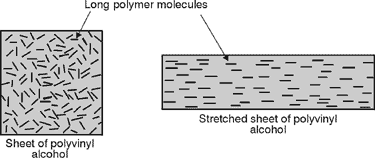
Transverse wave Plane polarization Vertical polarization Horizontal polarization Circular and elliptical polarization Dichroic polarizer Reflection polarizer Double-refraction polarizer Quarter-wave plate Half-wave plate Polaroid polarizer Thin-film polarizers Glan-Foucault polarizer Glan-Thompson polarizer Nicol polarizer Rochon prism polarizer Cubic beamsplitter polarizer Wollaston prism polarizer Glan-type polarizer Wollaston polarizer Reflection-type polarizer
Assume that each polarizer has a maximum transmission of 92.0%. Also assume that the"perfect" linear polarizer would transmit one half of the incident unpolarized light irradiance striking it. Sodium light source 2 Polaroid sheet-type polarizers 2 Polarizer mounts (rotatable) Glass plate with tilt stand (index of refraction » 1.50) Glan-type polarizer Mount for Glan polarizer Ground glass screen Screen holder Wollaston prism Prism holder 2 Optical benches Optical power meter Polaroid-type Polarizers
Glan Polarizer
Fig. 28
Fig. 29
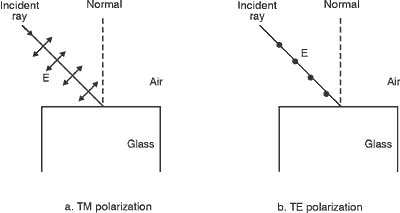
Austin, Russell. "Thin Film Polarizing Devices," Electro-Optical Svstems Design. Feb. 1974. Jacobs, Donald. Fundamentals of Optical Engineering. McGraw Hill Book Co., 1943. Jenkins, Francis A., and Harvey E. White. Fundamentals of Optics, 4th Edition. New York: McGraw-Hill Book Company, 1976. Pedrotti, Frank L., and Leno S. Pedrotti. Introduction to Optics. Englewood Cliffs, NJ: Prentice-Hall, Inc., 1987.
|


