|
Module 6-6 FILTERS AND BEAM SPLITTERS © Copyright 1987 by The Center for Occupational Research and Development All rights reserved. No part of this book may be reproduced in any form or by any means without permission in writing from the publisher. The Center for Occupational Research and Development Printed in the U.S.A. ISBN 1-55502-024-0 (1) A filter is a device that separates a substance trying to flow through it by allowing part of the substance to be transmitted while selectively inhibiting the transmission of the rest. Filters are used with liquids (such as gasoline and water) to remove solid impurities. Electrical filters restrict the frequency spectrum of current flowing in a circuit. Optical filters are used to transmit specific frequencies, uniformly reduce the intensity of a light beam or control the beam’s polarization. (2) Common examples of colored filters are the filters on colored spotlights for lighting fountains, buildings and theatrical stages. Examples of attenuation filters are sunglasses and tinted windows. (These examples also may include polarization and color isolation.) The envelope of a heat lamp is used as a filter to pass infrared rays and reject the transmission of ultraviolet and most visible rays. (3) Optical filters are used in many laser/electro-optical applications where accurate numerical measurements are needed. This requires that filter characteristics be accurately controlled and specified. You must know accurately the degree of attenuation reflection or polarization induced by the filters as a function of frequency. (4) This module will familiarize you with the functional classification of optical filters, the various types of filters within each classification, the advantages and disadvantages of each type and how to specify and use them. (5) Before you study filters and beam splitters, you must know basic laser eye safety. You should have studied elements and operation of a laser and laser safety. (6) When you complete this module, you should be able to do the following.
DISCUSSION (7) Several of the applications of scientific optical filters are in photography, optical communication, radar systems, holography, and general laser and electro-optical laboratory experiments. (8) Filters can be classified into three categories, according to the way they’re used:
(9) The following discussion will be organized to describe filters and their uses according to these classifications.
Attenuation Filters (10) Attenuation filters are used to reduce the intensity of a light beam. High-quality attenuation filters are said to have a "flat response." This means that they attenuate all wavelengths of light over their usable spectral range by the same amount. (11) Attenuation filters are used over a photosensitive surface when the light signal received is too intense. This would prevent overdriving a photodetector or overexposing photosensitive film. You can use calibrated attenuation filters to determine if the photosensitive surface is reacting linearly to the exposure. (12) An example of this application is a light signal being measured by a photodetector. If the photodetector is responding linearly, the insertion of a 50% attenuation filter in the light beam should cause a 50% reduction in the output electrical signal. (13) Attenuation filters can be divided into two groups according to the mechanism used to reduce the beam power.
Geometrical Filters (14) In the first group are those filters that physically block a fraction of an aperture through which the light beam passes. If you assume that the beam is uniform in intensity across the aperture, then the percentage of the aperture area that’s blocked is the percent reduction in beam power. (15) One example of a geometrical filter is the iris diaphragm, shown in Figure 1a. The iris or "stop" is used to reduce the aperture of a light beam. Consequently it reduces the transmitted beam power.
Fig. 1 (16) Another example is the screen or mesh filter, shown in Figure 1b. This type of geometrical filter actually breaks the relatively large beam into many smaller ones, resulting in a nonuniform distribution across the large aperture in the near field immediately preceding the screen. However, as the beam travels farther away from the screen, it becomes more uniform. Because of the possible development of undesired interference patterns caused by this type of filter, it’s wise to use it only near the detector. When used properly, however, such filter screens can reduce the light level in front of imaging systems without significantly reducing the resolution of the system.
Neutral-density Filters (17) Neutral-density filters are uniform, "grey" filters that absorb and/or reflect a fraction of the energy incident upon them. The term "neutral" is designated because the absorption and/or reflection characteristics of the filter are constant over a wide wavelength range. Fig. 2 (18) It’s useful here to define "optical density" as it applies to filters. Optical density is the degree of opacity of a translucent medium. It is given by the equation OD = –log10T where T is the transmittance of the filter. (19) Table 1 lists the values of optical density for transmission filters. Note, for example, that if the transmission through the filter is 10%, the transmittance is 0.1 and the corresponding optical density is A filter with 100% transmittance quite properly has an optical density of 0. (20) When light travels through a filter, a part of the beam is reflected at the two air-glass interfaces (plastic-air interface of gelatin filters) and another part of the beam is absorbed. Assuming that scattering and fluorescence are negligible, the remainder of the irradiance is transmitted through the filter. Accordingly, the following equation is applicable:
Table 1. Optical Densities of Transmission Filters
(21) Neutral-density (ND) filters usually are rated in optical density (OD) numbers. If two or more ND filters are used together, the density of the composite of the filters is the sum of their individual filters. As an example, if three filters of ND 0.1, 0.3, and 0.4 are stacked together they comprise an effective 0.8 ND filter.
Plastic or Gelatin Neutral-density Filters (22) Several types of ND filters are available. The most inexpensive (and commonly used) type of ND filter is the plastic or gelatin filter. These often are called No. 96 Wratten filters by the Eastman Kodak Company. These filters are made of colloidal carbon dispersed in gelatin. They can be purchased in two-, three-, and four-inch square sheets, 0.1 ± 0.01 mm thick. The calibration on neutrality of these filters is valid for the visible wavelengths only. M-type carbon, gelatin filters are also available. They can be used in the near ultraviolet, visible and near infrared. However, the M-type filters use larger carbon particles (~1m ) and tend to slightly scatter a light beam. If you must use ND filters on an image-forming beam, it is recommended that you use the No. 96 type filters. (23) You can get gelatin filters easily in densities from 0.1 – 4.0. You can specially order them with densities as high as 6.0. Although the gelatin film filter is protected by a thin lacquer coating, you should handle it only by the edges and extreme corners. Keep it flat and stored in a dark, dry place. Continued stress can deform it permanently, and moisture tends to cloud it. If you must cut the filter, place it between two pieces of clean, fairly stiff paper and cut with a sharp pair of scissors. (24) To maintain the stability or calibration of the filter we recommend that you not subject it to temperatures above 120°F. The output of high-power lasers (pulsed lasers exceeding roughly 0.1 joule and CW lasers exceeding 0.1 watt, depending on beam diameter) should not be used directly on gelatin film ND filters. Such laser outputs will permanently damage the filter. (25) You also can get gelatin film filters cemented between glass plates. This keeps the surface from being easily scratched. Cemented filters are lacquered on the edges to resist the entry of water, which will cause the gelatin to swell and separate from the protective cover.
Absorbing Glass, Neutral-density Filters (26) Neutral-density filters made of absorbing glass are also available. A typical example of this type is the Schott "NG series" glass. (See Figure 3.) The neutrality of these filters is valid to a wavelength of ~ 2.8 mm. These filters are more rugged than the gelatin type. They are less susceptible to scratching and offer more resistance to damage from high-power laser radiation. These filters are also much less susceptible to damage from high temperature than the gelatin film filters. They can be cleaned similarly to other optical glass. (27) The most likely possibility of a defect in these filters is inhomogeneity of the glass. You can detect inhomogeneities by looking through the filter toward intense light and inspecting for streaks and bubbles in the glass. Corning Glass Company manufactures similar types of colored and neutral-density glass filters.
Metallic Film on Glass (28) Metallic-film ND filters have the flattest response over a wide range of all the classes of filters. These filters are composed of a vacuum-deposited metal film on a glass or quartz substrate. (Quartz is used if we want to operate the filter near UV wavelengths.) Most manufacturers use the alloy inconel (nickel-chromium-aluminum) for the deposited films. Fig. 3 (29) Attenuation is by both reflection and absorption. You must consider the reflected beam energy in any application if there’s any chance of it being reflected in an undesirable direction. (30) These filters generally are not susceptible to changes brought about by temperature or aging. They may be used for extended periods at temperatures from –50°C to 120°C. Damage will occur if the temperature reaches approximately 160°C. The filters operate over a wavelength range from 0.275 mm to 2.5 mm.
Filter Wheel (31) For applications such as holography, it’s often convenient to have a way to continuously vary the intensity of a light beam. One way to do this is by use of a "filter wheel" as shown in Figure 4. (32) This particular variable ND filter is produced with a variable-density evaporated aluminum coating deposited on 270° of the disc. The remaining 90° is clear. The aluminized surface of the wheel is protected with an Si0 overcoating. The opposite side is AR coated (reflectance less than 0.75%, 450 nm to 700 nm). Because much of the light is reflected rather than absorbed by the metallic coating, these wheels can be used as variable beam splitters as well as filters. The substrate material is either BK7A crown glass or OPTOSIL-1 quartz. Fig. 4
(33) The most complete description of the optical behavior of a filter is given by its spectrophotometric curve (also called transmittance): that is, a plot of wavelength versus transmittance. An example of a family of rather idealized spectrophotometric curves for a specific absorption filter is shown in Figure 5. Fig. 5 (34) For absorbing filters, the transmittance is an exponential function of thickness,
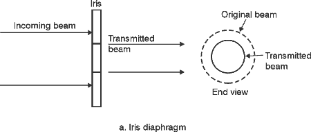
(35) The product t1t2 sometimes is called the "filter correction factor." For light incident normally on the filter surface, it’s given by,
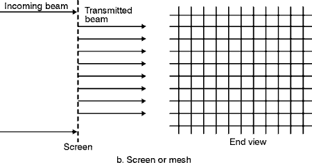
where: n = index of refraction of the filter glass (relative to air). (36) The top curve in Figure 5 is for a filter two millimeters thick. The second curve is for a filter four millimeters thick. It has 63.2% less transmittance. The top curve in Figure 5 transmits light at 500 nm very well. But is would transmit very little light at a wavelength less than 440 nm or greater than 560 nm. Fig. 6 (37) This type of filter is much different in its transmission characteristics from that of the neutral-density filter shown in Figures 2 and 3. The idealized ND filter in Figure 2 has a "flat" response from 300 nm to 900 nm. This flat region is called the neutral region. (38) Wavelength-selective filters—such as those shown in Figure 6—are used to produce or select specific color or band of color from a white light source, to isolate a specific wavelength, or to reject a specific wavelength or band of wavelengths. We will study three general classes of wavelength-selective filters according to their usefulness:
(39) We have introduced wavelength-selective filters according to the characteristics of their spectrophotometric (or transmittance) curves. These filters can be physically described by grouping them according to the way they alter the light, as follows:
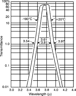
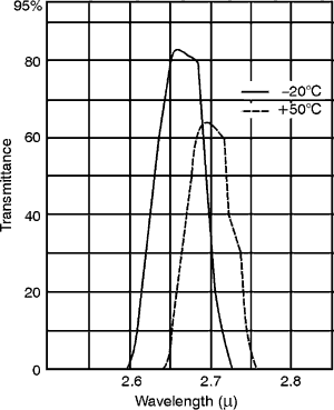
Interference Filters (40) Interference filters for wavelength selection are used when you need sharp cut-off or very narrow bandpass. They often are called "spike filters" or "narrow-pass" filters. They generally are made by depositing alternating layers (thin coatings) of dielectric materials on a glass or quartz window. Selection of materials and thickness of the coatings are chosen to provide reflection or transmission at the desired wavelengths. When the number of layers is increased, the cut-off or the passband becomes sharper, but the peak transmittance also decreases. An interference filter may have as many as 30 layers of coatings. These multilayer coating techniques are the same as are used to produce high-reflective laser mirrors. (41) Absorption and scattering from these surfaces is less than 1%. Consequently, when these coatings are used as filters, practically all of the light is either transmitted or reflected. The reflective properties constitute the filter. Since the transmitted beam shows negligible distortion from the interference coating, these filters can be used in imaging systems. (42) Compared to metallic films, many interference coatings are quite resistant to damage from high-power lasers. However, they are vulnerable to mechanical and chemical damage. Because they are easily scratched, they should not be wiped with lens tissue. You can remove dust by blowing clean, dry air across them or by gently wiping with a soft, camel’s hair brush. Do not wash them in water but rather clean them by pouring clean, dry ethyl alcohol, (preferably "nano grade," one part in 109 contamination) over the surface and allowing it to drain and evaporate. It’s best to store them in a dry container. Poor-quality coatings will develop cracks with age. Recent improvements have been realized in developing "hard" coatings that won’t scratch or wipe off as easily. A good, hard coating should not be damaged when a piece of masking tape is applied to the surface and removed (a standard "MIL spec" test). (43) Normally, an interference filter is designed to be used at 0° angle of incidence. The spectrophotometric curve of these filters can be shifted to longer or shorter wavelengths by varying the temperature and/or the angle of incidence at which they are used. To a lesser extent, the shape of the curve also is altered by these variations. (44) The curve of a multilayer interference filter shifts toward shorter wavelengths as the angle of incidence increases. The magnitude of this shift depends on the type of filter (bandpass, long-wave-pass, short-wave-pass, etc.), the filter design, and the refractive indices of the coating materials used. The relationship between "percent shift to shorter wavelength" and "angle of incidence" is shown graphically in Figure 10. The crosshatched area represents the variation in this relationship: Figures 11, 12 and 13 show the measured incident angle effects on three typical infrared filters. For incident angles up to about 40° , the shape of the curve is not appreciably distorted except for a slight decrease in transmittance. (See Figures 11 and 12.) However, when the incidence of angle becomes greater than 40°, changes begin to occur due to polarization effects and increased mismatch in the optical thickness of adjacent layers. (See Figure 13.) Fig. 10 Fig. 11 Fig. 12
Fig. 13 (
Fig. 14 ( Fig. 15
Fig. 16
Fig. 17 Combination Absorption/Interference Filters (47) In the following typical application, it’s desirable to use a very narrow passband fiIter with a low rejection ratio outside the passband.
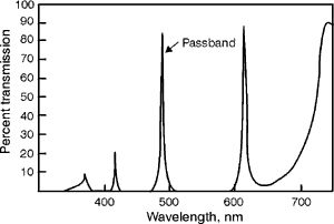
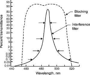
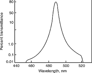
(48) Very narrow transmittance passbands can be achieved in interference filters by increasing the number of layers of dielectric coatings. An example of such a filter is shown in Figure 18. It is used for isolating the 488-nm argon laser line from the 514.5-nm line. Note that there are four other transmission lines also in this filter that don’t affect this line isolation. However, if you want to isolate this line from a broad, continuous light source such as the sun, then it’s desirable to:
Fig. 18
(
Fig. 19
Fig. 20 (50) The absorbing filter is called a "blocking filter" because it blocks out the other four transmittance bands and it reduces the width of the passband. Blocking filters can reduce the reflection ratio of the filter to 10–5. (51) Narrow-passband filters often are called "spike" filters because of the shape of their transmittance curve. As previously discussed, these filters are available with a half width of 0.1% or less of lc. As an example, a spike filter with a central transmittance wavelength of 1.06 m (output wavelength of Nd:YAG laser) could have a 2.0 nm FWHM or less. In these very narrow spike filters, the peak transmission is reduced to approximately 40 to 50% instead of the usual 70 to 80% for those filters with FWHM that are 2.0% of the central wavelength.
Polarization Filters (52)
We can make the following
Beam Splitters (53) A beam splitter is a device that’s used to divide an optical beam into two or more components according to given criteria. Beam splitters can be grouped into the following four classifications. These classes include those beam splitters that divide the beam size according to beam intensity, wavelength, polarization, or physical size. (54)
The most common beam splitter is a partially
reflective mirror. This mirror allows a predetermined percentage
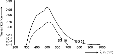
of the light to be transmitted while reflecting the remaining portion.
The actual percentage of the beam reflected and transmitted depends
on the coatings applied during the manufacturing process. Coatings commonly
available include inconel and achromatic dielectric. Beam splitters
with these coatings can be made to give a transmitted to reflected beam
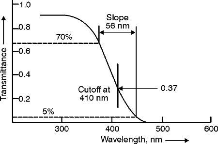
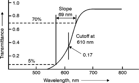
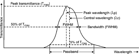
ratio of 30% – 70%, 40% – 60% and 50% – 50%. Variable-density
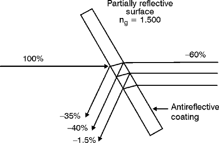
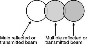
beam splitters (55) Partially reflective beam splitters have serious limitations. They provide a high loss factor, multiple reflections and distortions. To understand these limitations see Figure 21. Multiple reflections cause both the reflected and transmitted output beams to look similar to the cross-sectional views shown in Figure 22. Areas where the beams overlap produce interference patterns when the incident light is monochromatic, coherent laser light. If the light is not monochromatic, coherent light, ghost images can be produced.
Fig. 21
Fig. 22 (56) Distortion also can be introduced by a beam splitter that’s not made of the highest-quality material or by one that is not perfectly flat. (57)
A pellicle is a precise optical component that works like
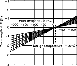
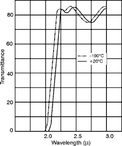
the partially reflective glass beam splitter. It is made of a plastic
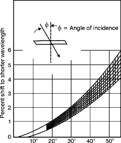
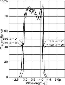
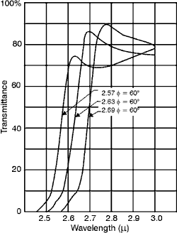
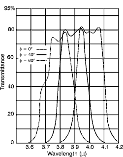
membrane stretched over an optically flat metal frame. The membrane
has a thickness of approximately 7 microns. Because of their thinness
and flatness, pellicle beam splitters demonstrate
several advantages over glass beam splitters. For example, they produce
almost no change in the optical path length of a light ray that occurs
when thick glass beam splitters are used. The thin plastic membrane
provides (58) Dichroic
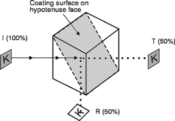
cube beamsplitters have been in use for a long time. They are constructed
by cementing together two right-angle prisms with an appropriate interference
coating deposited on the hypotenuse surface. The absorption in the coating
is very low so that the reflected portion and transmitted portions approach
50% each. The prism materials are generally made of BK7 glass with a
quarter-wave MgF2 coating on the outside surfaces of the
beamsplitter. They are available from most optical vendors in cube sizes
varying from
Fig.
23 (59)
The dichroic cube beamsplitter is also available as a polarizing
cube beamsplitter, transmitting 90% of one linear polarization and
essentially 0% of the other, over a wavelength range from 625 nm to
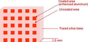
725 nm. Available cube sizes vary from (60) A recently-developed beamsplitter, the so-called polka-dot beam splitter offers a 50-50 split over a large spectral range, covering the UV to mid-1R wavelength regions. Polka-dot beam splitters are not polarization sensitive orincident-angle sensitive, working well with incident light angled at up to 45° from the normal. In addition, since they are only 1.5 mm thick, there is little energy loss. The polka-dot appearance comes from a rectangular array of coated-to-uncoated square surface areas—as shown enlarged in Figure 24—with enhanced aluminum as the coating over half of the square-sized apertures. The rectangular array has a UV-fused silica base. The input beam is split evenly, with 50% transmitted through the uncoated-fused-silica glass.
Fig.
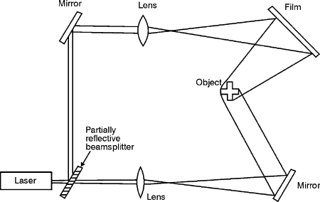
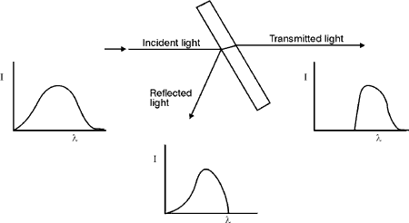
24 (61) Holography and interferometry are very important applications for partially reflective beam splitters. Figure 25 shows a typical arrangement of optical components for exposing a hologram. Note the position and function of the beam splitter. Fig. (62) Certain types of dielectric filters can be considered to be beam splitters because they divide a beam according to its wavelength. The dielectric coating permits wavelengths longer than a specified value to be transmitted. It reflects wavelengths shorter than that value. Figure 26 illustrates this type of beam splitter. Notice that the graphs in the figure show the relationship of the intensity of the respective beams as a function of the wavelength of that beam. Fig. 26 (63) Certain optical solids
known as birefringent crystals separate a randomly polarized light beam
into two plane polarized components. The crystal presents a different
index of refraction to each polarized component, causing the components
to be refracted at different angles. As a result, the polarized components
exit the crystal in separate directions. One of these two polarized
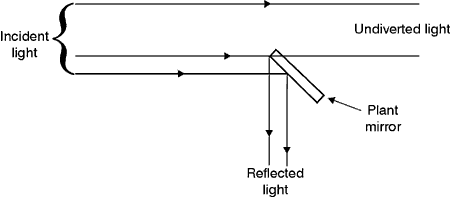
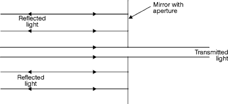
components is called the "extraordinary ray" Fig. 27 (64) The final beam splitter to be discussed in this module is one that divides a beam according to its position or geometry. For instance when a mirror is placed in a portion of a light beam it obviously will reflect the part of the beam that strikes it while leaving the remaining part of the beam undiverted. Figure 28 illustrates this beam splitter more fully.
Fig. 28 (65) The beam splitting mirror arrangement shown in Figure 29 sometimes is used as the output coupler on a CO2 laser.
Fig.
1 helium-neon laser, 1 mW 1 power meter, range 1 mW to 1 mW 1 set of Kodak Wratten 96 neutral-density filters—ND 3, 2, 1, 0.9, 0.8, 0.7, 0.6, 0.5, 0.4, 0.3, 0.2, 0.1 1 filter holder and stand 1 helium-neon spike filter, lc = 633 nm 1 rotary mount for spike filter, with scale calibrated in degrees in plane of rotation 1 lab jack
Data Table 1. Neutral-density Filters
Data Table 2. Transmittance at Normal Incidence
Data Table 3. Effect of the Angle of Incidence on the Transmittance
Corning Glass Filter Catalog, Corning, NY. CVI Laser Corporation Laser Products Catalog. CVI Laser Corp., 200 Dorado Place, SE, Albuquerque, NM 87192,(505)296-9541. "Ealing Opties Catalog," Current Year, Cambridge, MA. Kingslake, Rudolf. Applied Optics and Optical Engineering, Vol. I. NY: Academic Press, 1965. The Newport Corporation Catalog No. 100. Newport Corporation, 18235 Mt. Baldy Circle, Fountain Valley, CA 92728-8020, (714) 963-9811. Optical Coating Laboratory, technical report entitled "Effects of the Variation of Angle of Incidence and Temperature on Infrared Filters," Santa Rosa, CA, November 1962. "Optical Filters Designers Guide and Catalog," Waltham, MA: Infrared Industries, 1973. Optical Filter Catalog. Bedford, MA: Baird Atomic, 1972. Optics Guide 3. Melles Griot, 1770 Kettering Street, Irvine, CA 92714, (714) 261-5600 Oriel Corporation Catalog Vol. III. Oriel Corporation, 250 Long Beach Blvd., Stratford, CT 06497-0872, (203) 377-8282. Schott Glass Catalog, West Germany. Wood, R. W. Physical Optics. 3rd Edition, NY: Dover Publications, 1961.
|

