| This version reflects the comments of the core participants as reviewed and incorporated in accordance with CORD's FIPSE-supported Curriculum Morphing Project. | |||||||||||||||||||||||||||||||||||||||||||||||||||||||||||||||||
MODULE 4-3 General Comments of John
Simcik
When you complete this unit, you will be able to: 1. Describe the differences in the current/voltage characteristics of an argon ion laser as compared to a helium-neon laser. 2. Draw a block diagram for an argon laser power supply. Identify and explain the major components. 3. Draw the basic elements of a transistor passbank and describe its operation. 4. Explain the dependence of the multiline output power on the tube current. 5. Describe the principles of the current-regulated mode and light-regulated mode for stabilization of the output of an argon ion laser. Compare the performance characteristics of the two modes. 6. Explain the function of the magnetic field used with an argon ion laser. 7. Describe the function and operation of the starter circuit for an argon ion laser. 8. Discuss the environment in an argon laser tube and discuss how the tube design deals with the issues raised by this environment. 9. Draw a circuit for a helium-cadmium laser. Describe the functions of the major components. 10. Locate and identify the major components of an argon laser, given a list of the components and the operations manual for the laser. 11. Measure the multiline output power of the argon laser as a function of tube current and compare the measured results to what is expected. 12. Operate the laser in its current-regulated mode and in its light-regulated mode, measure the fluctuations in the laser output in each mode, and compare the results for the two modes. 13. Replace transistors in the transistor passbank portion of an argon laser power supply according to instructions in the operating manual for the laser.  Basics of Noble Gas Ion Lasers
A noble gas ion laser consists of a plasma with a glow discharge at high current density passing through it. The most common ion laser uses ionized argon as the laser medium. A number of different laser wavelengths may be emitted simultaneously. The strongest laser transitions are at 488 and 514.5 nm. Unlike the helium-neon laser, for which the energy levels are those of neutral atoms, the relevant energy levels are those of singly ionized argon gas. The lowest energy level is the ground state of the argon ion, which lies 16 eV above the ground state of the neutral argon atom. In addition, the upper energy levels lie about 20 eV above the ionic ground state. Thus, a considerable amount of energy must be supplied to the neutral argon atom to raise it to the upper laser level for laser operation. The output power available from commercial argon lasers ranges from a few tenths of a watt to 25 watts. The beam is usually a diffraction-limited TEM00 mode. The output power of an argon laser usually is specified in terms of a multiline output, that is the sum of the powers in all the wavelengths that are simultaneously present in the output (488, 514.5 nm, and so on). Table 1 indicates the split between the different wavelengths present in a nominal 20-watt argon laser. Single-line operation is possible if one adds a wavelength-selecting element, such as a prism, to the laser cavity. Because of the dispersion of the prism, only one wavelength will be incident normally on the mirrors so only that wavelength will operate. Selection of any particular wavelength is accomplished by rotating the prism. The output power will be reduced from the multiline power, to a value comparable to the contribution of the selected line to the multiline output. Thus, if a multiline 20-watt argon laser is constrained to operate at 514.5 nm, the output power may be only slightly greater than the 8.5 watts indicated in Table 1. Argon lasers also offer outputs in the 334- to 364-nm wavelength range. This makes the argon laser one of the few commercial sources of continuous ultraviolet laser light. Table 1. Representative Ion Laser Output
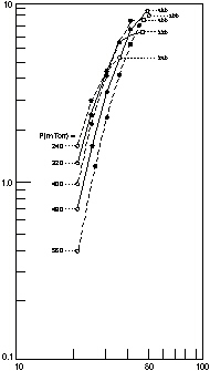
The argon laser has higher gain than the helium-neon laser, and much larger amounts of power may be extracted from it. The output power scales nonlinearly with the current density, so that it is desirable to operate argon lasers with a narrow bore and a high electrical current. Current densities up to 700 A/cm2 or even higher may be employed in argon lasers. The high current density produces heating and erosion of the plasma-tube walls, and thus strongly influences the design of argon lasers. Krypton ion lasers are very similar in construction and characteristics to argon lasers. Commercial models with continuous multiline output powers up to 16 watts are available. Table 1 presents the split between the power in the different lines of a nominal 14-watt krypton laser in multiline operation. In single-line operation, the krypton laser provides somewhat lower output power than an argon laser. The main reason for choice of a krypton laser instead of an argon laser would be to obtain a different variety of wavelengths, particularly wavelengths in the red and yellow portions of the spectrum, at power levels above those of the helium-neon laser. Mixed-gas lasers containing both argon and krypton are available and provide a composite choice of wavelengths. Such mixed-gas lasers provide lines in the red, green, and blue portions of the spectrum and thus are suitable for full-color displays. Other noble gas ion lasers have been demonstrated, in addition to argon and krypton, with similar characteristics. Examples are the neon ion laser, operating in the ultraviolet, and the pulsed xenon ion lasers operating in the green. These other noble gas ion lasers are much less common than argon and krypton. Perhaps one of the dominant features of the argon laser is its requirement for high electrical current density. This feature dominates the argon laser tube design and power supply requirements. The power output for an argon laser as a function of tube current for a number of different gas pressures in the tube is shown in Figure 1. At low values of current, the curves indicate that the output increases about as the fourth power of the current. At higher values of current, the curves overlap and the increase is less rapid, about as the square of the current. The slowing of the rate of increase probably is caused by depletion of the population of neutral argon atoms.
Fig. 1
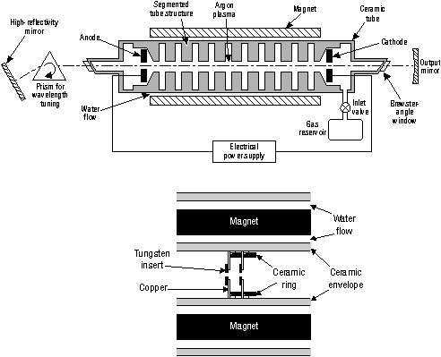
An approximate empirical (that is, derived from experient), relation for the specific power output P/V of an argon laser is: P/V = 10- 5 J 2 (Equation 1) where P/V is the power P emitted per unit volume V of the gas in W/cm3 and J is the current density in the tube (A/cm2). As a specific example, if we apply this equation to the conditions of Figure 1, we have: Tube diameter D = 0.4 cm Tube cross-sectional area A = p D 2/4 = 0.13 cm2 Tube volume V = 0.13 ´ 71 = 9.23 cm3. At a tube current of 50 A, the current density J = 50/0.13 = 385 A/cm2 and the relation predicts P/V = 10-5 ´ 348 ´ 348 = 1.48 W/cm3 or a total power output of 1.48 ´ 9.23 = 13.7 W, not too different from the approximately 10 watts that one would read from the figure. Thus, the relation is useful for predicting approximate power output of an argon laser for specified circumstances. The essential point of the figure and the equation is that to maximize the power output of an argon laser, the current density in the laser tube must be as high as possible. This makes the conditions inside an argon laser hostile. The high current density leads to sputtering of materials in the laser tube, to erosion of the surfaces, to electrode degradation, to contamination of the gas, and to trapping of gas atoms in the walls of the tube. The design of argon lasers has been an evolutionary process, with laser engineers using various approaches to solve these problems. The issues of the high current-density requirement lead to the following stressing issues for the laser tube: • The bore of the tube must be fabricated from a high-temperature material that will resist erosion by the electrical current. • Electrodes must be designed to withstand the discharge current, typically in the 50- to 200-amp region. They must be resistant to electron and ion bombardment. • Since positive ions are attracted to the cathode, resulting in unequal gas pressure along the bore, gas bypass channels must be provided to help equalize the pressure. • The tube must withstand very large thermal loads, of the order of 500 W/cm of length. There must be adequate provision to remove this heat. • Since the gas pressure is reduced continually by atoms being embedded in the inner surface of the tube, there must be means for replenishing the gas. Materials used to define the bore of an argon laser must be resistant both to high temperature and to sputtering by the electrical discharge. A common design involves use of electrically isolated radiation-cooled annular segments of material to confine the discharge, enclosed in a vacuum envelope. The material that most commonly is used for the segments is tungsten. The envelope is usually alumina ceramic, formed as a single seamless cylinder. Alumina offers high strength, good electrical insulating properties, and high thermal conductivity. Most modern argon lasers operating at relatively high levels of power employ conductive metal disks brazed to the ceramic tube. The internal structure of the tube is fabricated from segments. The bore is defined by central holes in annular tungsten disks. The tungsten is resistant to sputtering and to high temperature. A design for a such a segmented argon laser tube is shown in Figure 2. Each bore segment has a thickness less than one centimeter, a hole in the center to define the discharge region, and holes around the central opening to allow for gas return. The segments are stacked together inside the ceramic tube. Various approaches for supporting the segments have been devised. The bottom of the figure shows the approach of one manufacturer to mounting the disks. The tungsten inserts define the bore, which confines the discharge and forms the optic axis of the tube. Copper is used for the supporting structure because of its high thermal conductivity. Openings in the copper allow the return gas flow. In a different design, the bore is defined by annular tungsten disks with holes in them to allow return gas flow. The disks are brazed to copper cups that in turn are brazed to the ceramic tube. The anode of the laser tube is usually a metal ring inside the ceramic envelope. It is bombarded by electrons. Since the electrons have little mass, they do not erode the anode too quickly. The cathode is often a coiled tungsten ribbon coaxial to the optic axis. The cathode is heated to an orange glow by electrical current to produce a cloud of thermally emitted electrons around it. Positive ions attracted to the cloud capture electrons and become neutral atoms. If the electron cloud were not present, the bombardment of the cathode by energetic ions would destroy it quickly.
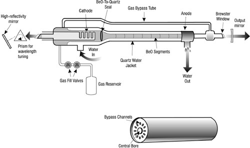
Fig. 2 Figure 2 also shows the wavelength-selecting prism, which allows operation on a single one of the wavelengths available. Without the prism, multiple wavelengths would be present in the output simultaneously, as Table 1 has indicated. A design for a relatively low-power argon laser is shown in Figure 3. This uses beryllium oxide (BeO) segments as the high-temperature ceramic material. BeO has proven to be resistant to erosion by the current and offers high thermal conductivity for heat removal. The tube is formed of BeO segments. One such segment is shown in the bottom portion of the figure. A segment typically may be one centimeter in diameter and several centimeters long. The tube is formed by sealing a series of such segments together with ceramic. One end of the tube is sealed to a quartz section that contains a heated cathode, a ballast volume, and the gas fill port. The other end terminates in a metal section that serves as the anode and water outlet port. A quartz extension holds a Brewster window and is attached to a gas bypass tube that leads back to the cathode end. The BeO segments are enclosed in a quartz water jacket. Figure 2 has indicated the presence of a magnet surrounding the laser tube. The solenoidal magnet induces a longitudinal magnetic field, parallel to the optical axis of the tube. The magnetic field causes electrons to move in orbits around the field lines. Fewer electrons drift to the walls of the tube. This has the effect of confining the current near the center of the tube and increases the current density there. This increases the power output of the laser. The optimum magnetic field has been found experimentally to be around 1000 Gauss. Many commercial argon lasers, especially multiline lasers, have preadjusted optimum magnetic field to maximize multiline output. Some commercial lasers do have controls that allow the user to vary the magnetic field to optimize the output for specific single-line operation.
Fig. 3 Argon lasers require active cooling. Forced-air cooling may be used in relatively low-power models, but water cooling is employed at higher levels of power. Usually water flows along the length of the tube, as Figures 2 and 3 have indicated. The water-flow rates are typically a few gallons per minute, up to about 7 gallons per minute for the largest commercial argon lasers. Sensors monitor the water-flow rate and the temperature of the outlet water. The water-flow sensors will shut off the laser if the flow is disrupted or the water temperature rises too high. The cooling-water system usually contains a filter to remove contaminants from the input water. The argon gas is depleted in the course of operation, so that gas refill reservoirs are included in the design of many argon lasers. When the argon pressure drops below a specified value, the operator activates the refill system to restore the pressure to the specified value. The requirement for large electrical current and the rather complicated structure of the tube make the argon laser more prone to failure than the long-lived helium-neon laser. The manufacturers’ warranties for argon lasers are shorter than for helium-neon lasers. The operating lifetimes of argon lasers before failure are typically several thousand hours.
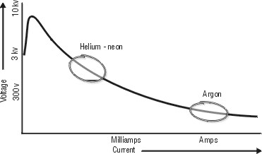
Power Supplies for Noble Gas Ion Lasers Argon and krypton ion lasers have different power requirements than do the gas lasers considered in Module 4-2. The lasers considered in that module, helium-neon, carbon dioxide, metal vapor, and excimer, all operate at high voltage and with relatively low current. The noble gas ion lasers require much higher current to achieve the necessary amount of ionization. Ion lasers may draw 10 to 70 amperes of current, depending on the output power required. But typical operating voltages are low, perhaps around 2200 volts. Figure 4 shows the current/voltage characteristics of a gas discharge again, with the relative regions for operation of helium-neon lasers and argon lasers indicated for comparison. In the region where ion lasers operate, a change of 1-2 amperes in tube current may result in a voltage change of only a few volts.
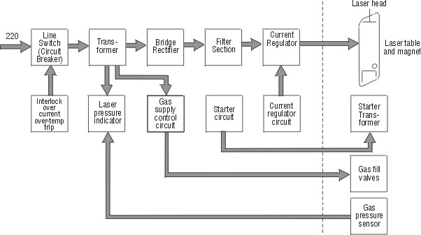
Fig. 4 Figure 5 shows a block diagram for a typical argon ion laser power supply. The power supply is known as a buck-boost design. The line switch is a circuit breaker that may be tripped by a signal from any of several safety and current protection devices. The functions of these safety devices will be discussed later. The transformer is usually an autotransformer with several input taps. Changing taps allows the user to obtain an output of 220 V for input voltages between 200 and 240 V.
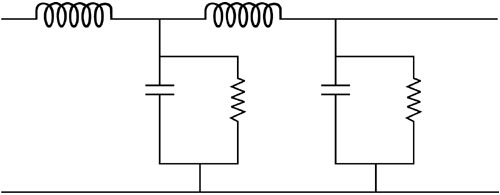
Fig. 5 The next stage is a full-wave rectifier circuit, which converts the AC input to DC. Bridge rectifiers already have been described in Module 4-2. The output of the rectifier is fed to a filter section, which smooths out ripple. The filter is typically an LC choke filter of the type shown in Figure 6.
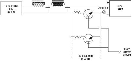
Fig. 6 One of the important features in the power supply is the current regulator, which compensates for changes in the line voltage and keeps the laser-tube discharge constant. The current regulator is important for minimizing fluctuations of the current in the tube and thus reducing fluctuations in the laser output power. In perhaps the most common approach, the current is limited and controlled by a transistor passbank (also referred to as a pass transistor bank). A schematic diagram of such a bank is shown in Figure 7. The figure shows only two transistors, but a practical bank would consist of 10 to 30 transistors in parallel. The number would depend on the amount of current that the bank must handle. The collectors of all the transistors are wired in parallel and connected to the laser tube through an ammeter. The bases are connected in parallel and receive a controlling current from the current-sensing circuit. A small resistor (around 3 ohms) is connected in series with each emitter to equalize the current through the transistors.
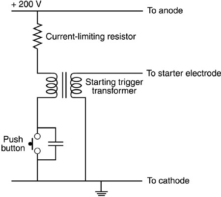
Fig. 7 The current-regulator circuit includes a current-sensing element. The signal from this sensor is amplified and applied to the base of the transistors in the passbank. This controls the voltage drop across the transistors, and thus the current through the bank. The current-regulator circuit also includes an output control that is used to set the desired current through the laser tube. Current from the passbank may both drive the discharge and energize the magnets around the laser tube, although in some some models, the magnets may have their own separate power supply. In some commercial lasers, the regulator circuit uses operational amplifiers to control the drive current to the transistor passbank. A portion of the passbank current is fed to the input of the operational amplifiers to provide closed-loop control of the tube current. Use of a transistor passbank as a current regulator provides the lowest-noise operation for an ion laser. However, transistor passbanks are relatively expensive. Thus some manufacturers have employed banks of multiple silicon-controlled rectifiers (SCR) as current regulators. The SCRs are relatively inexpensive and provide a reasonable cost/performance tradeoff. Although the ion laser requires around 200 volts to sustain a steady discharge, it needs a higher voltage to break down the neutral gas and initiate the discharge. This feature is in common with the other gas lasers we have described. A breakdown voltage of several kilovolts is needed to start the discharge. Figure 8 shows a diagram of a simple circuit that can provide the starting voltage. When the push-button switch is closed, current flows through the primary of the trigger pulse transformer. The current is limited by the current-limiting resistor. When the starter switch is returned to the open position, the current stops abruptly. The magnetic field in the transformer collapses. This produces a high-voltage pulse in the secondary of the transformer, which is connected to a starter electrode in the tube. This may be a separate third electrode in the tube, although some tubes use the anode as the starter electrode.
Fig. 8 Figure 9 illustrates a more sophisticated starting circuit that has been employed in commercial argon lasers. After a delay to allow the cathode to heat to its operating temperature, voltage from the AC line is applied through a silicon-controlled rectifier to a pulse transformer. Thus from a 60-Hz line, the transformer will receive 60 pulses per second. The secondary of the transformer powers a half-wave rectifier bridge. The output of the rectifier goes to a spark gap, which breaks down as the voltage exceeds its threshold (about 7.5 kV). Then the high voltage is applied across the coil to the anode of the laser tube. This begins the breakdown of the gas in the tube. The direct-current power supply then takes over and sustains the discharge. As current begins to flow from the passbank, a sensor turns off the silicon-controlled rectifier and removes the starting voltage.
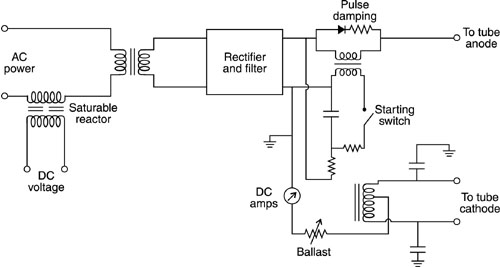
Fig. 9 An alternate configuration for a direct-current argon laser power supply that uses a saturable reactor is shown in Figure 10. The saturable reactor is attractive because it provides high open-circuit voltage for easy starting, but also offers automatic current limiting under short-circuit conditions. The starting pulse comes from a capacitor discharge through a winding of the final filter choke. The diode and resistor provide pulse damping to eliminate ringing. This helps ensure that the main power supply will take over the discharge when the starting pulse decays.
Fig. 10 The operating pressure in an ion laser is typically a few hundred millitorr. The gas is depleted during laser operation. The high current drives some gas atoms into the walls of the tube, trapping them there. This leads to a decrease in the amount of gas in the tube and eventually to a decrease in laser output power. Thus, additional gas must be added after some hours of operation. Argon lasers incorporate a gas reservoir, often with solenoid-controlled valves and sometimes with key operation. The user may add gas to the tube when the gas is depleted. Many ion lasers include a pressure gauge that the operator can use to determine if more gas is needed and to monitor the filling process. Gas should be added when the tube is warm to avoid overfilling. Two types of gas-fill systems commonly are used in argon lasers. Both are illustrated in Figure 11. The left side of the figure shows a two-valve system, in which two solenoid-operated valves are separated by a short length of tubing with a known volume. When the "ready" valve is actuated, a predetermined volume of gas enters the volume between the two valves. Then when the "fill" valve is actuated, this gas enters the laser tube.
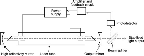
Fig. 11 The single-valve system is shown in the right portion of the figure. It uses one solenoid-operated valve that has a preset cycle time. The output end of the valve is connected to a stainless steel capillary tube that leads to the laser tube. When the valve is opened momentarily, gas flows into the capillary tube. The resistance to gas flow is set so that the proper amount of gas flows into the laser tube during the open time of the valve. Both types of system usually are designed to increase the gas pressure by about ten millitorr at a time. Some ion lasers have automatic gas fill systems. One variation employs gas-pressure sensors that activate the valves and add gas until the proper tube pressure is reached. Another variation monitors tube current and voltage. If the tube pressure changes, the tube voltage will change without a corresponding change in the tube current. The voltage change then is used to activate the automatic gas fill. Another function performed by the ion laser power supply is control of the power output to reduce fluctuations in the output. Ion lasers have high-frequency noise fluctuations in their output power. The noise spectrum extends up to 2 MHz. An important function of the power supply is to minimize these fluctuations. Many commercial argon lasers have two different control modes, which can be selected by the operator: Current-regulated mode. In this mode the plasma current is held constant. Output power fluctuations may occur because of changes in the resonator, the optics, the ambient temperature, and so on. Light-regulated mode. The output power is controlled by using a detector to monitor the output power and changing the tube current to compensate for changes in output. The current-regulated method involves setting the output to any desired level between threshold and maximum power by adjusting the current through the plasma tube. The control then is exercised by the current-regulator portion of the power supply, e.g., the transistor passbank, which stabilizes the current. This mode is relatively simple and permits good power stabilization adequate for many applications. It does require manual adjustment for any resonator or optical variations that may cause changes in the laser power. The current-regulated mode can achieve control of laser power fluctuations (specified as the root mean square value) to levels ranging from a few tenths of one percent to a few percent, depending on the particular laser and its current-control design. In the light-regulated mode, the operator sets the output to the desired level. A small portion of the output power is picked off by a beam splitter and directed to a photodetector, as shown in Figure 12. The output of the photodetector is fed into a feedback circuit, which amplifies the signal and compares it to a steady reference voltage. If the light output changes, the variation is detected by the electronics. An error signal is generated that is used to adjust the tube current to maintain the desired laser power. The resulting control improves both the amplitude noise fluctuations and the long-term stability of the laser.
Fig. 12 The operation of the photodetector must be highly stable. The photodetector usually is contained in a sealed enclosure to prevent dust and dirt from affecting its operation. In some argon lasers the photodetector is contained in a temperature-controlled oven to improve its stability. The light-regulated mode provides tighter control of the fluctuations in laser output
power than does the current-regulated mode. The fluctuations Argon lasers have a variety of interlock features that protect both the operator and the equipment. Interlocks on the covers of the laser head and the laser power supply automatically turn the power off if the covers are opened. There also may be a room interlock, which turns the laser off if the room door is opened during laser operation. Other safety interlocks are designed primarily to protect the equipment. We have alluded to some of these earlier. The equipment interlocks include sensors that turn off the laser if any of the following conditions exists:
The exact set of interlocks that may be present varies from one model of laser to another, but the above list will give an idea of what is common. The interlock system in some argon lasers is driven from an auxiliary transformer that is activated as soon as the system key switch is turned on. The sensors for the interlock system also may turn on indicator lights on the control panel when a fault is detected. The indicator light informs the operator of which interlock is causing the problem. The electrical input for ion lasers can range from 10-15 amperes, single-phase, 120-volt power for relatively small units to 70 amperes of three-phase current at 440 volts. The input requirements increase with increasing output power. A 5-watt multiline argon laser might require 10-20 kW of input power. A 1-watt krypton laser would take about the same input power.
Helium-Cadmium Lasers Another type of ion laser that we will discuss is the helium-cadmium laser, which employs as an active medium a vapor of the metallic element cadmium. The helium-cadmium laser is an ion laser because its laser operation uses the energy levels of ionized states of gaseous cadmium. In many of its characteristics however, it is similar to the helium-neon laser. The cadmium is vaporized by a heater. Keeping the metal in a vapor state without having it recondense is one of the common features of metal vapor lasers. The helium is present because it aids in the production of the population inversion. Aside from the necessity of working with a hot metal vapor, the operation and power supply requirements of a helium-cadmium laser are similar to those of a helium-neon laser. The excitation of the upper laser levels of the vaporized cadmium is produced in a manner very similar to the excitation of the neon levels in the helium-neon laser. In the electric discharge through the helium-cadmium gas mixture, helium atoms are excited by collisions with electrons. The excited helium atoms then collide with ground-state cadmium atoms. The collisions produce excited levels of the cadmium ion. The process is favorable for producing populations for two different laser lines, at wavelengths of 441.6 and 325 nm. Development of the helium-cadmium laser represented a great technical challenge because of the presence of a hot metallic vapor. Successful operation of the helium-cadmium laser requires production of a sufficiently high vapor pressure of cadmium metal, good control of the vapor in the discharge, prevention of chemical reactions between the hot cadmium vapor and other tube components, and avoidance of deposition of cadmium metal on the optical surfaces. A substantial amount of engineering work has led to simple, reliable, and compact commercial helium-cadmium lasers. The helium-cadmium laser represents a compact, continuous source of visible laser light at relatively low levels of power and can be used for applications similar to those of the helium-neon laser, except at a shorter wavelength. The 325-nm line has been useful for lithographic applications. The cadmium metal is contained in a reservoir near the anode end of the tube. The reservoir is heated to give the desired vapor pressure of cadmium. The electric discharge is ignited in the helium gas. The discharge produces cadmium ions. The ions migrate from the anode end of the tube toward the cathode in a process called cataphoresis. The cadmium metal recondenses near the cathode end of the tube as the vapor cools. Cold traps are provided near the cathode to help reduce the condensation of the metal at undesired places, like windows and mirrors.
Power Supplies for Helium-Cadmium Lasers Helium-cadmium lasers operate in the same general range of the current/voltage curve as helium-neon lasers. The current required for the helium-cadmium laser is typically around 100 milliamperes. The tube voltages range from 2000 to 5000 volts, depending on the characteristics of the tube. The power supplies for helium-cadmium lasers are similar to those of helium-neon lasers, except that the current capabilities are higher. In contrast to helium-neon lasers, which usually have grounded cathodes, it is usually desirable to operate the helium-cadmium laser with a grounded anode. A common method of achieving this is a circuit similar to that shown in Figure 6 of Module 4-2 but with the diodes reversed. Because of the higher current requirements, the resistors in the RC filter would dissipate large amounts of current. Thus, the RC filter is replaced by an LC filter. Figure 13 shows an example of a power supply for a helium-cadmium laser. The current regulator in this power supply is a transistorized current regulator. This both limits the tube current to safe values and allows better control of the current.
Fig. 13 Figure 14 shows one example, out of many possible, of a current-regulator circuit. The diodes remain nonconducting as long as the voltage across them remains less than the forward threshold voltage. If the load current IL increases, the voltage across R rises. When it rises to the point where the diode threshold voltage is reached, the base current is diverted from the transistor. The result is that the voltage across R is limited to a maximum value determined by the diode threshold voltage. The starter for helium-cadmium lasers is usually the same as the internal type for helium-neon lasers, as discussed in the previous module. Small helium-cadmium lasers emitting a few milliwatts of power at 441.6 nm require about 160 watts of input power. Larger models, operating in the 100-milliwatt range require several hundred watts of input power. Heating of the cadmium metal to provide the necessary vapor pressure may require a few tens of watts of additional electrical power. Most commercial helium-cadmium lasers require 120-V AC wall-plug power, but some higher-power models may use 220 V AC.
Fig. 14
Argon ion laser with current-mode and light-mode control Argon ion laser operating instruction manual Argon laser safety goggles Beam block Optical power meter compatible with ion laser Photodetector with high-speed (microsecond) response and power supply Personal computer with curve-fitting program software Oscilloscope and cables Transistors compatible with transistor passbank for the argon laser Fuses compatible with transistor passbank for the argon laser Thermal grease (Wakefield 120-8 or equivalent) Torque wrench 
1. In the first part of the procedures, you will identify components in an argon ion laser. Before the scheduled lab period, the major components of the argon laser will be located and identified. Sufficient time will be given for you to become familiar with the location and identification of these parts. During the scheduled lab period, you will locate and identify each of these components in the presence of the instructor:
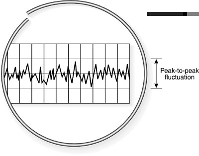
Also identify and explain each control and indicator on the power-supply front panel. 2. In the second part of the procedures, you will measure the multiline output power of the argon laser as a function of tube current. Before the start of the lab period, you should have read the entire operating instruction manual for the argon laser. Observe all recommended safety precautions during the laser operation. Be sure that the beam is terminated by a beam block or by the power meter at all times. Observe the laboratory rules regarding use of laser protective eyewear. Before the lab period, the wavelength-selecting element should have been removed so that the laser is in multiline operation. Turn on the laser in accordance with the instructions in the operating manual. Direct the beam into the sensor of the power meter. Set the tube current to a relatively low value, just above the threshold for laser operation. Measure the current using the current meter in the laser control section. Measure the output power. Then increase the tube current in steps, up to the maximum recommended value, and measure the output power and current at each step. For each measurement, record the current and the power. After the end of the lab period, enter the data on current and output power into the curve-fitting routine on the personal computer. Use the curve-fitting routine to obtain a power law fit to the data. Compare the exponent in the power law fit to the expected value. 3. In this portion of the procedures, you will operate the laser in its current-regulated mode and in its light-regulated mode. You will measure the fluctuations in the laser output in each mode and compare the results for the two modes. Direct the beam into the aperture of the photodetector and feed the output of the photodetector into the oscilloscope, which should be free-running. Set the controls of the laser to the current-regulated mode, following the instructions in the operating manual. On the oscilloscope trace, measure the voltage corresponding to the average power of the laser and the peak-to-peak voltage fluctuation corresponding to variations in the output. This may require some trial-and-error adjustment of the sensitivity and sweep speed of the oscilloscope. The average value is best measured with the scope DC coupled. The voltage scale is set to a relatively large value, so that the trace is on the screen, both when the beam is present and when it is blocked. Note the position of the trace when the beam is blocked and measure the deviation from this position when the beam is present. The voltage fluctuation is best measured with the scope AC coupled, and with the sensitivity control at a value corresponding to a smaller number of volts/division than in the previous measurement. Set the sensitivity control so that the peak-to-peak variations in the signal are all on the scope face. Set the sweep speed so that a number of peaks is visible at one time. Since the noise spectrum extends to a frequency as high as 2 MHz, a sweep speed around 10 microseconds/division could be suitable. The appearance of the scope face should be similar to what is sketched in Figure 15. Measure the peak-to-peak voltage fluctuations. Record the measured values.
Fig. 15 Set the controls of the laser to the light-regulated mode, following the instructions in the operating manual. Repeat the measurement of the voltage corresponding to the average laser power and to the peak-to-peak fluctuations. Record the measured values. When the measurements are complete, shut down the laser in accordance with the instructions in the operating manual. Calculate the percentage fluctuation for the current-regulated mode of operation and for the light-regulated mode. Use the formula:
4. In the final part of the procedures, you will replace transistors in the transistor-passbank portion of the argon laser power supply. This operation should be performed according to the instructions in the operating manual for the particular laser available. The procedures for a model INNOVA 90 argon laser from Coherent, Inc. are summarized below as an example, but they will have to be modified for different laser models. For the INNOVA 90, the transistor passbank contains a driver transistor plus 23 transistors in parallel. The transistors are mounted in sockets and fused with a 4-ampere fuse for each transistor. The power supply can operate with the loss of up to two failed transistors. If a third transistor fails, the power supply will shut down and the transistors must be replaced. When a transistor fails, the fuse associated with it will blow. A transistor-failure circuit senses the blown fuse and activates a diagnostic light on the control module that informs the operator that a fuse in the transistor passbank has failed. A light-emitting diode on the passbank lights to indicate which transistor has failed. Prior to the lab period, the instructor will have inserted three failed transistors in the passbank. Loosen the thumb screw that holds the drawer that contains the passbank. This will reveal a switch marked TEST-RUN. Turn the switch to its test position. Turn on the key switch on the control module. The light-emitting diodes associated with the failed transistors will light. Note their locations. Turn off the key switch and disconnect the power cord from the wall plug. Then remove the screws that hold the transistors in their sockets and remove the transistors from the sockets. Inspect the area for dirt or metal filings and clean if necessary. Replace the transistors with the appropriate type (2N6259 for the INNOVA 90 laser). Coat the bottom of the transistors with the thermal grease and install them in the sockets. Replace the screws, and tighten them evenly. For the INNOVA 90 they should be torqued to 6 inch-pounds. Locate the fuses associated with the failed transistors and replace them with the appropriate type of fuse (4 ampere for the INNOVA 90). Reconnect the power cord and turn on the key switch. No light-emitting diodes should be on. Turn off the key switch and turn the TEST-RUN switch to RUN. Push the passbank drawer into the chassis and tighten the screws. The power supply now should be functional. Turn it on and check its operation. 
Measurement of power versus tube current Tube current Power 1. 2. 3. 4. 5. 6. 7. 8. 9. 10. Measurement of percentage fluctuations
Current-regulated mode Voltage corresponding to average power Voltage corresponding to peak-to-peak fluctuations
Light-regulated mode Voltage corresponding to average power Voltage corresponding to peak-to-peak fluctuations

1. Describe the differences in the current/voltage characteristics of an argon ion laser as compared to a helium-neon laser. 2. Draw a block diagram for an argon laser power supply. Identify and explain the major components. 3. Draw the basic elements of a transistor passbank and describe its operation. 4. Explain the dependence of the multiline output power on the tube current. 5. Describe the principles of the current-regulated mode and light-regulated mode for stabilization of the output of an argon ion laser. Compare the performance characteristics of the two modes. 6. Explain the function of the magnetic field used with an argon ion laser. 7. Describe the function and operation of the starter circuit for an argon ion laser. 8. Discuss the environment in an argon laser tube and discuss how the tube design deals with the issues raised by this environment. 9. Draw a circuit for a helium-cadmium laser. Describe the functions of the major components. 
Bridges, W. B. "Ionized Gas Lasers." Handbook of Laser Science and Technology, Volume II, Gas Lasers, ed. M. J. Weber. Boca Raton, FL: CRC Press, Inc., 1982. CW Ion Lasers. Fremont, CA: LaserSonics, n.d. Hecht, J. The Laser Guidebook. New York: McGraw-Hill, Inc., 1992. _______. "Ion lasers deliver power at visible and UV wavelengths." Laser Focus World, 28/12 (December 1992): 97. Sinclair, D. C., and W. E. Bell. Gas Laser Technology. New York: Holt, Rinehart and Winston, Inc., 1969.
|
|||||||||||||||||||||||||||||||||||||||||||||||||||||||||||||||||

