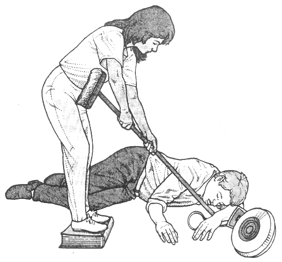
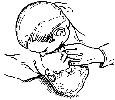
| This version reflects the comments of the core participants as reviewed and incorporated in accordance with CORD's FIPSE-supported Curriculum Morphing Project. | ||||||||||||||||||||||||||||||||||||||||||||||||||||||||||||||||||
MODULE 4-1
Safety concerns with lasers have typically emphasized the hazard potential to the eyes and skin from optical radiation. However, the electrical-shock hazards associated with the use of lasers and electro-optic equipment require special attention. Many accidents related to laser operation and maintenance have involved electrical hazards rather than optical hazards. The potentially lethal effects of electrical shock make the electrical hazards more dangerous than the optical hazards. Knowledge, safe operating procedures, hazard recognition, simple safety procedures, and proper measurement techniques can significantly reduce electrical-safety problems. Obvious electrical hazards associated with the use of laser systems include the high-voltage, direct-current power supplies for continuous lasers, and the high-energy storage capacitor banks used in the power supplies of many pulsed lasers. The physiological effects of electrical shock must be understood before a discussion of electrical safety is presented. This module will discuss the physiological effects of electrical shock, the factors affecting the severity of electrical shock, the electrical hazards of laser systems and laser-related equipment, electrical safety standards, control measures, and the appropriate procedures to take following an electrical accident. The student should have completed a course in basic sensing electronics and should have a firm understanding of Ohm’s law, capacitor discharge characteristics, and current and voltage laws.
When you complete this unit, you will be able to: 1. List three ways electrical shock can kill and describe factors associated with each. 2. Explain why capacitors found in many high-voltage power supplies pose a unique potential hazard. Given typical capacitor and resistance values for a laser system, calculate the discharge time constant, and draw a curve of charge on the capacitor versus time. 3. List and explain the factors affecting the degree of electrical shock. 4. Describe operating procedures appropriate for working with electrical equipment. 5. Describe electrical safety devices incorporated in laser-related equipment and explain the purpose of each. 6. Discuss electrical safety equipment and explain how each type would help prevent electrical shock or be used for the handling of a victim after an electrical accident. 7. Explain the appropriate response activity after an electrical accident for:
8. Describe the ABCs of cardiopulmonary resuscitation techniques necessary for a victim of electrical shock. 9. Learn the cardiopulmonary resuscitation techniques necessary for a victim of electrical shock by attending a course taught by certified instructors. 10. Measure the charging and discharging characteristics of an energy-storage capacitor. Demonstrate appropriate electrical-safety practices during the measurements.
Physiological Effects of Shock A variety of factors affects the severity of the injury associated with electrical shock. These include the magnitude of the current, the path of the current through the body, the duration of the shock, the frequency, whether the shock involves an alternating current, and the varying susceptibility of the heart to damage in different portions of the heart’s cycle.
Effects of Current The amount of electrical current flowing is what causes the damage, not the voltage. The voltage, of course, determines how much current flows through a path with a specified value of electrical resistance, but the current is what does the damage. A high voltage by itself is not necessarily associated with severe injury, provided that the amount of current flowing is small. The main obstruction to flow of electrical current in the human body is the resistance of the skin. Dry skin has an electrical resistance of tens of thousands of ohms. This value drops substantially if the skin is moist, to a value of a few thousand ohms. Thus it is much easier to receive an electrical shock if the skin is wet at the point of electrical contact. The interior tissues of the body are moist and salty, and hence are good conductors of electricity. The resistance of the interior of the body, from one major limb to another, is typically a few hundred ohms. Thus, if the resistance of the skin is broken down, the flow of electrical current can increase considerably. The amount of current I that flows is given by Ohm’s law:
where V is the applied voltage and R is the resistance. The resistance is the sum of two terms:
where Rc is the contact resistance with the skin and Ri is the resistance of the interior of the body. The contact resistance is much higher than the internal resistance and is the factor that limits the flow of current. But, if the voltage is high enough, the contact resistance may be broken down and only the much smaller resistance of the interior remains, so the current may become much larger. The flow of electrical current is aided if the person is grounded, that is, is standing or sitting on a good electrical conductor. If someone is standing in water, for example, even a relatively low voltage can cause a dangerously high value of current to flow through the body. If someone is standing in a dry environment on a poor conductor and wearing shoes with insulating soles, the flow of current will be much lower. The flow of electrical current through the body may strongly affect the nervous system. Electrical current can cause loss of muscular control, convulsions, and paralysis. If the affected muscles involve the heart or lungs, the loss of muscular control may lead to coronary arrest or respiratory arrest, both potentially lethal conditions. The path of the current is extremely significant. An electrical current that flows through the heart may disrupt the heart function and cause a derangement of heart function called ventricular fibrillation. Ventricular fibrillation is an arrhythmia of the heartbeat, which results in the pulsations of the heart being unable to circulate blood through the body. It is potentially lethal within a few minutes. It may be caused by a flow of electrical current that is not large enough to cause severe tissue injury directly. An electrical current of around 100 milliamperes that flows through the heart can bring about this potentially fatal ventricular fibrillation. The burns produced by the passage of electrical current through the body tend to be deep burns, often to the point of charring the affected tissue. Burns may be the direct result of current flowing through the affected tissue, or of the heat released by large values of current. This is basically a joule heating effect. The heating and the charring are greatest at points where the resistance is highest. This is usually where the current enters and exits the body. Electrical shock can result in tissue injuries ranging from the onset of neurological deficits to charring to the disruption of heart function. Even in nonfatal electrical trauma, the tissue damage can lead to amputation of limbs. Electrical injury often occurs in skeletal muscle and nerve cells. Many observable signs in a victim with an electrical injury point toward neuromuscular damage. These signs include severe spasms and convulsions. Table 1 summarizes information on the values of current at which certain specified physiological phenomena occur. These are approximate values, and can vary from one person to another. The exact values for a particular individual will depend on many factors, including the exact path of the current through the body, the gender of the victim, and whether the current is direct or alternating. The thresholds for women tend to be somewhat lower than for men. Thresholds for alternating current tend to be lower than for direct current and depend on frequency, as we will describe later.
In summary, the passage of electrical current through the body has many dangerous effects. Potentially lethal effects include:
Effects of High Voltage Although it is the flow of current that causes injury, not the voltage itself, the voltage available will play a role in initiating and driving the current. The amount of current that flows is also determined by both the voltage and the electrical resistance of the body. The interior of the human body is a good conductor of electricity. But dry, intact skin has a high electrical resistance. No current flows when a relatively low voltage is in contact with the dry skin. High voltage can overcome the resistance of the skin and allow current to flow. Once the skin has been broken down, electrical current will flow through the body easily. As was discussed previously, if the skin is moist or wet, its resistance is lowered and it becomes easier for current flow to be initiated. Electrical fields are capable of damaging cells through both thermal and nonthermal effects. The most common cause of tissue injury in electrical trauma is joule heating, the thermal effect of an electrical current flowing through an electrical resistance. Skeletal muscle and nerve cells are the most susceptible to this type of damage. But large electrical voltages may have an additional effect. Direct electrical breakdown of cell membranes by high applied electric fields may also be a contributing nonthermal mechanism of damage. It is commonly accepted that large cells, such as muscle and nerve cells, are more vulnerable to electrical breakdown. This mechanism could cause cell damage, even if the current flow is low.
Voltage Classification The magnitude of the contact voltage with the victim is used to classify an electrical injury as either a high- or low-voltage injury. High voltage is arbitrarily defined within the medical community as any voltage above 1000 V. However, the extent of tissue damage or injury is a function of electric-field strength, or volts per meter, along the path of the current through the body. An apparent low-voltage contact may produce an electric field of a magnitude similar to those produced during high-voltage contact, and the injuries can be similar. The difference in the extent of the injury is the volume of tissue injured. Let us consider two examples. First, consider contact with a 20,000-V electrical power line, with the contact points being the two hands. The distance from entrance to exit is about 2 meters and the electric field is 20,000/2 = 10,000 volts/meter. The second example is a laboratory power cord (120 V) with the contact points 6 millimeters apart on one hand. The electric field is 120/0.002 = 10,000 volts/meter, the same value as in the first example. The first example would be considered a high-voltage injury and the second a low-voltage injury. But the strength of the electrical field is the same in each case and the nature of the damage to tissue would be similar. The first case would be much more dangerous, because the volume of tissue involved is much larger and the path of the current is near the heart, lungs, and thorax. Involvement of any of these parts of the body could be a potentially lethal situation. However, the charring of the tissue at the contact points and the damage to subcutaneous (below skin level) tissue will be the similar in both cases. Thus it is not the total voltage alone that is important, but the localized electric-field strength, which will also determine the extent of tissue destruction. Electric fields may damage cells through thermal injury or through electrical breakdown of cell membranes. The extent of damage is dependent on the electric-field strength, not the total voltage.
Effects of Frequency If the electrical shock is the result of an alternating current, the frequency of the current plays a role, at least if the duration of the shock is more than one second. The effect of the current is greatest for frequencies between 10 Hz and 200 Hz. The effects, for equal current, decrease at frequencies below and above this range. We note that the commonly available 60-Hz electrical-line voltage is within the range where effects are most severe. Table 2 presents data on the values of alternating electrical current that represent the point at which muscle control is lost and one cannot let go of the current source, the so-called let-go threshold. Let-go thresholds vary substantially from one person to another. The values in the table are the values at which 50 percent of people cannot let go. The values in the table are for men. Values for women are about two thirds of the values in the table. The let-go threshold is significant because it represents a level above which the victim cannot get free of the electrical source. Above this threshold, the current continues to flow through the body, increasing the duration of the exposure and the amount of damage to the body.
Duration of the Shock The duration of the shock is also important. As might be expected, the shock becomes more dangerous as it continues. For a given value of current, the effect is likely to be more severe and the thresholds for harmful effects to become lower as the shock is prolonged. Figure 1 shows how the duration of the shock affects the hazard of ventricular fibrillation for 60-cycle alternating current. As the duration of the shock lengthens from 0.1 to 100 seconds, the threshold current drops by more than a factor of 25. 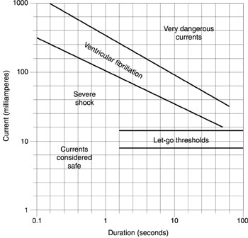
Fig. 1
Ventricular Fibrillation The timing of a short-duration shock relative to the phase of the cycle of the heart is also important. The heart is sensitive to ventricular fibrillation only during the so-called partial refractory phase of its cycle, which lasts about 20 percent of the total cycle. A short shock that does not overlap this portion of the heart cycle does not cause ventricular fibrillation.
Long-Term Effects Intense muscular spasms may continue for many hours, even days, after the exposure occurs. Muscle necrosis, or localized death of living muscle tissue, may continue well after the accident and eventually result in amputation of the affected region. Amputation is required in 45 to 65 percent of victims who show signs of muscle necrosis. The onset of a degenerative state of the nervous system, known as neuropathy, may occur months or even years after an injury. Neuropathy, including various forms of paralysis, has occurred even in the absence of direct injury to the central nervous system.
Electrical Hazards The sources of potential electrical hazard in a environment where lasers and electro-optic equipment are employed are many and varied. In many cases, they are not unique to laser research and application but are similar to other types of scientific, engineering, and industrial settings. The hazards may include the input power, the laser and electro-optic equipment with its power supplies, and especially energy-storage capacitors.
Input Power In most common laser applications, the input power is alternating current. Commonly encountered current sources for lasers and laser-related equipment include 120-V AC single-phase power, 208/220-V AC single-phase and three-phase power, and 440-V AC power. The level of hazard, of course, increases with the voltage.
Laser and Electro-Optical Equipment This equipment includes things such as laser power supplies, photodetector power supplies, Q-switch power supplies, modulator power supplies, and high-voltage switches. Laser power supplies often operate at very high voltages. For example, CO2 TEA lasers often incorporate sources with voltages in excess of 50 kilovolts. Voltages in this range are especially dangerous, because injury may occur without contacting the power supply directly. Voltages of this magnitude can cause an electric arc to form and allow current to flow across an air gap. Thus it becomes hazardous even to get close to a power supply operating at multikilovolt levels. Photodetectors have power supplies that may require high voltages. Photomultiplier tubes, for example, require voltages in excess of one kilovolt. Electro-optic modulators may also have voltages in the kilovolt range.
Energy-Storage Capacitors High-energy capacitors used with many pulsed lasers are a particularly grave hazard. They are often charged to voltages of several kilovolts and store energies from hundreds to thousands of joules. If a person comes in contact with such a capacitor, it is possible that its entire stored energy may discharge through the victim. The high voltage can break down the resistance of the skin. The discharge of the charge Q on a capacitor with capacitance C in a circuit with resistance R is given by: Q = Q0 exp (–t/RC), Equation 3 where Q0 is the initial charge and t is the time after the beginning of the discharge. Thus the charge decays to about 37 percent of its initial value after a time equal to the product RC. One generally approximates the duration of a capacitor discharge by RC. As an example, if C is 500 microfarads (perhaps a typical value for a small, pulsed solid-state laser) and the resistance of the body after the skin is broken down is 500 ohms (a typical value for the resistance of the body between major limbs), the time for the capacitor to discharge will be 500 ´ 500 ´ 10- 6 seconds or 0.25 second. The energy stored in the capacitor will thus discharge through the body in a very short time. The energy stored in such a capacitor charged to a voltage V of 2000 volts is 0.5 CV2, or 1000 joules. This is a potentially lethal amount of energy.
Electrical Safety Standards The National Electrical Safety Code (NESC) is the national standard for electrical safety. It covers the installation, maintenance, and operation of electric supply facilities. The NESC rules prescribe requirements necessary to reduce exposure to known and anticipated hazards to personnel and equipment. Work on the NESC began at the National Bureau of Standards in 1915. Since that time, it has undergone many revisions and updates. The NESC is prepared by a diversified group of active participants who represent a wide variety of industry and public viewpoints. The group combines a great depth of experience in a number of areas including construction, operation, maintenance, and applications. The rules are reviewed on a regular basis and revised to reflect changes in material or methods, with a stress on cost, utility, and practicality. The NESC does not intend to require more expensive equipment than good practice requires and good business practice justifies. The public, in the end, pays the higher cost when safer and better construction is required. The NESC promotes safety by uniformity of practice and emphasizes that adequate safety must be preserved by inspection and maintenance. Another standard, the National Electrical Code (NEC), has been developed by the American National Standards Institute under the sponsorship of the National Fire Protection Association. The NEC serves as a guide for the safe installation of electrical wiring and equipment and has broad national acceptance. Originally formulated in the late 1800s, the NEC has undergone many revisions and updates to keep current with changing and developing technology. The American National Standards Institute (ANSI) standard Z136.1 for the safe use of lasers is commonly accepted as the definitive standard dealing specifically with laser safety. This standard also deals with electrical hazards associated with lasers and related equipment.
Control Measures Although one cannot completely eliminate the dangers to personnel near electrical facilities, one can substantially reduce the hazard if good safety practices are employed and suitable safety devices and physical barriers are in place. Control measures to minimize electrical hazards take the form of operating practices, safety devices, and safety equipment.
Operating Practices There should be standard operating procedures for the hazardous electrical equipment in a given facility. These operating practices take the form of prescribed procedures for handling, operating, and maintaining specific pieces of equipment in a safe manner. In the following paragraphs, we discuss some desirable safety practices that help minimize the hazard of electrical shock. This does not constitute a complete set of procedures and practices. Suitable procedures should be developed for each installation with electrical hazards, taking into account the specific nature of the hazards in each location. One should use only one hand when performing any procedures with electrical equipment. The other hand should be out of the way and not in contact with any conducting material. This practice makes it less likely that an electrical shock will take a path through the chest from one arm to the other. The common expression is, "Keep one hand in your pocket." It is highly desirable to develop this practice into a well-established habit. When one touches any electrical equipment for the first time, it should be lightly, with the back of the hand. Thus, if any shock is incurred and results in an involuntary muscular contraction, the hand will be knocked away rather than prompted to grasp the equipment. Personnel working with electrical equipment should be trained in proper procedures. The training should include items such as the effects of electrical shock; wiring color codes; the ratings of wiring, switches, and so on; good wiring practices; and similar concerns. Unqualified and untrained personnel should not be allowed access to areas containing potential electrical hazards. A person should not work alone on electrical equipment. Another person should be present to give aid in case of an accident. It is best to wear shoes with good, insulating soles, and to stand on dry, nonconducting matting in good condition. One must avoid touching electrical equipment with wet or sweaty hands, and not wear rings, metal watchbands, or other metal objects when working with electrical equipment. Each circuit should be clearly labeled, and the location of the emergency switch to kill the circuit in an emergency situation should be clearly identified. The personnel in each area should be familiar with the location of the switches, cords, circuit breakers, and so on, in case it is necessary to kill the electricity quickly. In wiring circuits, one should use the proper wire size, with adequate current-carrying capacity to avoid overheating. Fuses or circuit breakers should be installed in electrical equipment to shut it off if it becomes overloaded. The use of adapters (or "cheaters") to plug three-wire power cords into two-prong receptacles should be avoided, and the condition of electrical circuitry should be checked regularly. Loose connections and worn or frayed cables should be replaced. A scheduled program of preventive maintenance for electrical equipment should be established, and should include careful inspection and repair of any faults. Flammable materials should be kept away from electrical circuitry, to reduce fire hazards in case of an electrical accident or overheating. Because of the especially dangerous nature of the high electrical energies stored in capacitor banks associated with lasers, special procedures are desirable when dealing with them. Energy-discharge capacitors should be enclosed in a well-grounded, locked metal enclosure, which should be designed to prevent accidental contact with any of the conductors inside it. It should also provide for automatic discharge of the capacitors before any access door is opened. This is done by shorting or grounding the capacitors with a heavy-duty conductor. (This is called "crowbarring the capacitors.") The crowbar should be able to withstand the large currents that flow and the large mechanical forces that will be exerted on it. Shorting straps should be placed on the capacitors before any maintenance work is done. When possible, workers should wait 24 hours after the capacitors have been crowbarred before beginning work on that circuit. They should be sure each capacitor is discharged, shorted, and grounded before beginning work. Banks of discharge capacitors should be enclosed in cabinets or housings that can withstand possible explosion of the capacitors.
Electrical Safety Devices In referring to electrical safety devices, we mean devices, circuits, or components that are built into laser and associated equipment to reduce hazards. This includes automatic crowbars built into circuits with energy-storage capacitors, as discussed above. In addition, bleeder resistors should be included in circuits with energy-storage capacitors. The bleeder resistors will slowly discharge the capacitor when it is not in use. An example is shown in Figure 2, which represents a simple flashlamp power supply for use with a pulsed solid-state laser. The capacitor C is charged by the charging power supply. When a trigger pulse is applied to the flashlamp, the capacitor will discharge through the flashlamp, creating a pulse of light that pumps the laser. The resistor R in the circuit is a bleeder resistor inserted as a safety measure. The bleeder resistor will gradually discharge the capacitor if the laser is not fired for some time. This ensures that a capacitor is not inadvertently left in a charged state. 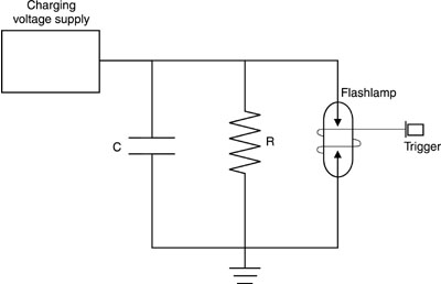
Fig. 2 The approximate time for the capacitor to discharge is RC, as discussed above. The value of the resistor should be as low as possible, so the circuit will discharge rapidly when not in use. But the value of R should be large enough that a small charge will bleed off the capacitor between pulses of the laser at its intended pulse-repetition rate. As an example, consider a circuit as shown in Figure 2, with the value of C equal to 500 microfarads. The pulse-repetition rate of the laser is intended to be one pulse per second. The product RC should be large compared to one second, but not excessively large. If one chooses to have the product RC equal to 100 times the pulse-repetition rate, very little charge will be dissipated between pulses. Thus, if we desire RC to be 100 seconds, then R ´ 500 ´ 10- 6 = 100, and R = 100 ´ 106/500 = 200,000 ohms. The capacitor will discharge according to Q0 exp (- t/100), where Q0 is the initial charge and t is the time in seconds. In this example, only a small amount of charge will be lost between pulses at the normal pulse-repetition rate, but the capacitor will be discharged to about 37 percent of its initial charge if the laser is not fired for 100 seconds and to about 13 percent of its initial charge after 200 seconds. This reduces the danger of leaving an energy-storage capacitor charged accidentally. Another recommended safety measure for capacitors involves the use of circuits that incorporate neon lamps and resistors as indicators to show the state of the capacitor’s charge. Other examples of recommended safety devices include:
Safety Equipment By safety equipment, we mean devices and components not incorporated into the electrical circuits and not specific to any particular laser or application. Rather, these pieces of equipment are of general applicability, useful for a variety of circumstances. An example would be a grounding stick with a resistor at its end and an insulating grounding cable permanently attached to ground. The resistor would be at the point of contact. A grounding stick limits the current flow to prevent damage to equipment. Such a device may be used to discharge small capacitors, but should not be used to discharge large capacitor banks. Other safety equipment should include:
Safety Training CPR Training Cardiopulmonary resuscitation (CPR) was "discovered" during the 1960s. In 1973, the American Heart Association identified CPR as a first-aid procedure that should be taught to the general public on a national scale. CPR training consists of studying written material, attending sessions taught by certified instructors, and practicing techniques on mannequins with the instructors as guides. (CPR should not be practiced on another person.) Contact your local Red Cross or American Heart Association to register for a CPR certification course. Like any skill, CPR must be practiced. CPR skills should be updated yearly or at least every two years. Promptly initiated, CPR can save lives within the first few minutes after "clinical death" (cessation of heartbeat and breathing). Brain damage begins only a few minutes after a person’s breathing and/or heartbeat have stopped. Brain death is virtually certain after 10 minutes of oxygen deprivation. Therefore, prompt application of CPR is critical. The following steps are necessary in a medical emergency:
1. Recognize signs of electrical shock, heart attack, or stroke. Electrical shock. Electrical shock may be relatively easy to identify, even if the victim is unconscious. Other personnel in the vicinity may have observed the incident, or the victim may still be in contact with electrical wiring or electrical equipment. Even if that is not the case, other indications may suggest the possibility of electrical shock. These include the victim’s proximity to unenclosed electrical wiring or equipment, open panels on electrical equipment, and so on. The presence of burns at the points where the electrical current entered and exited the body is also an indication of electrical shock. Often in electrical shock, the victim is thrown back and away from the electrical source by involuntary muscular contractions. The position and placement of the victim’s body relative to electrical equipment may thus be a clue to electrical shock. In other cases, if a person comes upon an unconscious victim and no one observed the accident, it may not be possible to determine whether the victim has received an electrical shock or is suffering from other problems. Before touching the victim, the rescuer should make sure the victim is not in contact with a source of electricity.
Heart attack. Chest discomfort is the most common sign of a heart attack. It may be described as pressure, squeezing, fullness, tightness, or pain. It may be in the center of the chest, behind the breastbone, or may spread to the shoulder, jaw, neck, or either arm. It will usually last longer than two minutes and may come and go. Other signs include sweating, nausea, shortness of breath, and weakness. Many victims do not exhibit typical warning signs. The discomfort may not be severe, and they may not look sick. Generally, sharp, stabbing, short-lived twinges are not a warning sign of heart attack.
Stroke. Sudden weakness or numbness in the face, arm, or leg on one side of the body may indicate a stroke. Loss of speech, trouble with speech, or slurring of speech are also stroke indicators. Signs may also include unexplained dizziness, unsteadiness, or falls. Vision, especially in one eye, may be affected. This can include dimness, blurriness, or loss of vision. Finally, loss of consciousness may occur.
2. Have another person call for emergency service As you begin emergency medical assistance, another bystander should call for emergency medical help (911 in most cases). The caller should describe what has happened, giving information about whether electrical shock, heart attack, or stroke is involved. The caller should describe the condition of the victim and what is being done to help. The caller must describe where the victim is, giving the exact address and directions, with landmarks if necessary. The caller should also give the telephone number from which the call is being made. If you are alone, you should begin CPR immediately, before telephoning for help, even if a telephone is nearby. Time is critical. After completing a CPR cycle, quickly make a call for help.
3. Provide immediate rescue procedures (CPR when indicated). In the case of electrical shock, do not touch the victim and do not begin first aid until contact with the source of electricity has been broken. Kill the source of electricity by tripping the circuit breaker or pulling the electrical plug. If this is not possible, push the victim away from the electrical source with a dry, nonconducting object, like a broomstick or long wooden board. While doing this, stand on a dry, nonconducting object such as a board. See Figure 3.
Fig. 3 If the victim is breathing and has a heartbeat, place the victim in the so-called recovery position illustrated in Figure 4. This is done in the following manner: Tilt the victim’s head back to keep the airway open. Put the arm nearer you by the victim’s side and slide it under the victim’s buttock. Place the other arm across the victim’s chest. Cross the leg farther from you over the nearer leg at the ankle, with one hand supporting the head. With the other hand, grasp the clothing at the hip farther from you, and pull the body toward you. Bend the upper arm and leg to support the body. Check to make sure the head is tilted back and the airway is clear. Leave the victim in the recovery position until trained medical personnel arrive.
Fig. 4 Note that if there are possible injuries to the neck or spine, you should not move the victim or place the victim in the recovery position. Loosen tight clothing and cover the victim with a coat or blanket to minimize heat loss. Do not give the victim anything to eat or drink. Continue to monitor the victim’s heartbeat and breathing. If the victim is not conscious and/or not breathing, begin CPR. CPR is a temporary action to be used in case the victim’s heartbeat or breathing has stopped and until more advanced life support becomes available. CPR combines chest compression and mouth-to-mouth breathing. It allows some oxygenated blood to reach the brain and other vital organs during the period before more sophisticated medical treatment can restore natural heartbeat and breathing. CPR includes three basic rescue skills, the so-called ABCs of CPR:
For the purposes of this module, the case of an adult victim with one rescuer will be discussed. However, a CPR certification course will cover the case with a child or infant victim and a case where there is more than one rescuer. An abbreviated summary of the procedures is given below, as an illustration. This will not replace the more complete instruction you will receive in your certification course. Case with one adult victim, one rescuer.
A — Airway
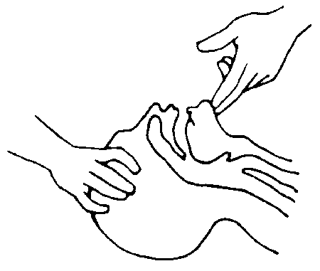
Fig. 5 • Open the airway. Tilt head back; lift chin up. • Check to make sure no object is blocking the airway.
B — Breathing
Fig. 6 • Deliver two rescue breaths by breathing into the victim’s mouth. Refill your lungs between breaths. Each breath should last one to two seconds. Watch for the victim’s chest to rise.
C — Circulation • Determine lack of heartbeat by placing two or three fingers in a groove below the chin between the Adam’s apple and muscle. This should take no more than five or ten seconds. • If there is no heartbeat, proceed with chest compressions. Run your finger along the victim’s lower ribs up toward the chest. Place finger where they meet at the sternal notch. • Place heel of upper hand slightly above the sternal notch. • Place other hand on top of the hand positioned in the last step. • Lock elbows and position your shoulders above your hands. • Compress vertically downward with your body weight. Depress the victim’s sternum 1.5 to 2 inches (see Figure 7). 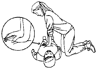
Fig. 7 • Release pressure, keeping hands in position between compressions. • Repeat the compressions at a rate of 60-100 compressions per minute, counting aloud to establish a rhythm. Count, "One and two and three and," and so on. • Complete 15 compressions, return to head-tilt position, and complete two ventilations. Then return to compressions. You should continue administering CPR for four cycles, each cycle consisting of two breaths and 15 compressions. After four cycles, you may make an emergency phone call if you have not been able to previously. You should not interrupt CPR for more than a few seconds, once you have begun. After four cycles, you should reassess the victim. Reassessment begins by checking for the return of a pulse for five seconds. If there is no pulse, resume CPR. If there is a pulse, check the breathing. If there is a pulse, but no breathing, resume rescue breathing, one breath every five seconds. If there are both a pulse and breathing, monitor the victim and get help if you were unable to do so previously. There are hazards to CPR. For example, incorrect positions could result in fractures, bleeding, bruising, and internal damage. Failure to release between compressions will prevent blood from circulating. It is possible that some sounds of cracking and popping may occur with properly administered CPR. Adult CPR is intended for persons more than eight years old and weighing more than 65 pounds. Children and infants, with more delicate structures, can be injured if the procedures described above are employed. Modified procedures have been developed for children and infants to reduce the possibility of such damage. Once you start CPR, you must continue. You may stop only when the victim recovers, when another trained person takes over, when emergency medical help arrives, or you are completely exhausted and unable to continue. Good Samaritan laws in many states protect lay persons who perform CPR in good faith.
4. Relinquish responsibility to trained emergency medical personnel when they arrive. Be sure that the personnel are really qualified, not merely well-intentioned but untrained bystanders. In summary, properly administered CPR can save lives. Training in CPR procedures is very desirable for personnel working in areas with potential electrical hazards.
DC power supply (capable of 1000-volt output) Energy-storage capacitor (50 microfarad) Digital multimeter Resistors (200, 500, and 1000 kohm) Switches (5 single pole, single throw) Stopwatch Electrical leads as required 
Contact the American Red Cross or other organization that provides CPR training. Register for and attend a CPR course taught by certified instructors. In the course you will learn and practice the cardiopulmonary resuscitation techniques necessary for a victim of electrical shock. In the laboratory procedures, you will measure the charging and discharging characteristics of an energy-storage capacitor. Demonstrate your knowledge of electrical safety practices by employing all appropriate practices. Set up the apparatus as shown in Figure 8, first shorting the capacitor and making sure that it is discharged. With switches S2, S3, S4, and S5 open, close switch S1. Set the power supply to 1000 V, and turn it on. Observe the voltage across the capacitor at intervals by opening switch S1 and closing switch S5. Record the voltage and the time as measured by the stopwatch. It may be necessary to run through this procedure in a preliminary trial to obtain an estimate of suitable measurement intervals. If so, discharge the capacitor after the preliminary run. 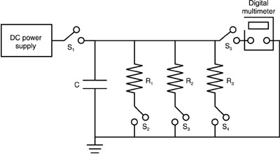
Fig. 8
After recording the voltage and time, open switch S5 and close switch S1 and continue charging. Repeat the cycles of charging, measuring, and recording until the capacitor is charged to 1000 V. Plot the results of the measurements of voltage versus charging time. Next, with the capacitor charged to 1000 V and with switches S1, S3, and S4 open, close switches S2 and S5. This allows the capacitor to discharge through resistor R1. Observe the decrease in capacitor voltage on the multimeter. Continue to measure until the voltage is near zero. It should be possible to make these measurements "on the fly" while recording voltage and elapsed time at suitable time intervals as the capacitor is discharging. If this is not possible, open switch S2 to make the measurements. Recharge the capacitor and repeat the series of measurements, discharging the capacitor through resistor R2 (switch S2 open and switch S3 closed). Repeat the series of measurements discharging through resistor R3. Plot the results of capacitor voltage versus time for the three resistors. At the end, short out the capacitor and make sure it is discharged.
CHARGING MEASUREMENTS Time (sec) Voltage (V)
DISCHARGING MEASUREMENTS Resistor 1 Resistor 2 Resistor 3
1. List three ways electrical shock can kill and describe factors associated with each. 2. Explain why capacitors found in many high-voltage power supplies pose a unique potential hazard. If a laser system incorporates a 1000-microfarad discharge capacitor and a 1-megohm bleeder resistor, calculate the discharge time constant. Draw a curve of charge on the capacitor versus time, normalizing to unity for the initial charge. 3. List and explain the factors affecting the degree of electrical shock. 4. Describe operating procedures appropriate for working with electrical equipment. 5. Describe electrical safety devices incorporated in laser-related equipment and explain the purpose of each. 6. Discuss electrical-safety equipment and explain how each type would help prevent electrical shock or be used for the handling of a victim after an electrical accident. 7. Explain appropriate response activity after an electrical accident for:
8. Describe the ABCs of cardiopulmonary resuscitation techniques necessary for a victim of electrical shock.
Clapp, A. L. NESC Handbook: A Discussion of the National Electrical Safety Code. New York: Institute of Electrical and Electronics Engineers, 1992. CRC Handbook of Laboratory Safety. Boca Raton, FL: CRC Press, 1990. Dalziel, C. F., and W. R. Lee. "Lethal Electric Currents." IEEE Spectrum, February 1969, 44. Kuehl, G., and D. Halligan. CPR: The Way to Save Lives. Cardiopulmonary Resuscitation. St. Louis: J. D. Heade Co., 1987. McPartland, J. F., and B. J. McPartland. National Electrical Code Handbook. 21st ed. New York: McGraw-Hill, Inc., 1993. National Electrical Safety Code. New York: Institute of Electrical and Electronics Engineers, 1993. National Safety Council. CPR Manual. Boston Jones and Bartlett, 1993. Safe Use of Lasers. American National Standards Institute Standard Z136.1 (1993). Orlando, FL: Laser Institute of America, 1993. Sliney, D., and M. Wolbarsht. Safety with Lasers and Other Optical Sources, Chapter 28. New York: Plenum Press, 1980. Swann, H. W. Electrical Safety. New York: Philosophical Library, 1959. U. S. Department of Labor, Occupational Safety and Health Administration. Controlling Electrical Hazards. Washington, DC: Government Printing Office, 1991. |
||||||||||||||||||||||||||||||||||||||||||||||||||||||||||||||||||


