Processor-Enhanced Communications
Digital signal processing (DSP) is not entirely new. digital processes have been used for many years to compress data files, correct data errors and digitize sound and video, and to enhance signal reception. Demand for increased performance spurred the development of specialized devices designed just for this application. The initial applications of these devices have produced exciting real-time results that have attracted a great deal of attention in recent years.
The devices we call digital signal processors are actually special-purpose microprocessors optimized for certain functional operations used in digital numeric signal processing. As microprocessor technology continues to advance and converge, we may find ourselves calling these devices signal coprocessors.
Digital Signal Processing (DSP) with Analog Modulation
Signals and signal modulation are analog in nature. The amplitude, frequency and phase of a signal can be varied continuously over a range of values. So-called analog modulation systems use the continuous variability of signals to encode variable instantaneous values directly.
The problem with analog modulation is that noise and interference cause disturbances in the instantaneous received amplitude and phase values, which corrupts reception of the information being sent. Although the impact of some types of noise can be held within limits, in analog systems there is generally no way to know whether any particular change in amplitude or phase value was caused by noise, or was actually part of the information being sent.
Still, there are ways to minimize the audibility of noise in an analog system. Most of us have seen and heard the popular DSP filter boxes, and these can really clean up received signals.
Bandpass, High-Pass and Low-Pass Filtering
Narrow selectivity is an old technique, but DSP can do it better. The older techniques of resonant filtering are ingenious, but suffer from excessive ringing when taken to extremes. These "Infinite Impulse Response" (IIR) designs literally never stop ringing, although in practice the ringing usually falls below any level of importance fairly quickly. The problem is that when extreme selectivity is used, the ringing does not fall off rapidly enough.
DSP systems can duplicate the IIR filters, but can also produce "Finite Impulse Response" (FIR) filters. Properly designed FIR filters do not produce excess ringing, although there is still a limit to the selectivity that can be applied. But the elimination of excess ringing with FIR filters allows narrower selectivity to be used.
DSP can produce very sharp cutoff filters. The filter parameters are stable and repeatable. Depending on the sophistication of the system, ultimate attenuation can reach 120 dB or more.
Autocorrelation
Speech sounds change slowly compared to the waveforms of their various frequency components. These frequency components persist long enough to detect and identify their spectral components. The popular DSP autocorrelation noise reduction technique responds to the spectral features of incoming signals by building a dynamic multiple bandpass-band reject filter which passes frequencies with continuous energy and rejecting frequencies without continuous energy. This allows speech and CW signals to pass reasonably freely, while blocking much of the hiss and most short-duration ticks.
It is also possible to set up an autocorrelation filter to produce a notch where there is a very long term spectral peak in the signal. If this rejection response to very long term spectral peaks is slow enough, speech sounds will not be affected, but continuous heterodynes will be rejected.
The FFT and Dynamic Spectral Manipulation
The FFT (Fast Fourier Transform) is process which converts a time-varying signal into its frequency components, and vice-versa.
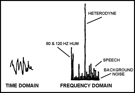
DSP can use the Fast Fourier Transform to analyze sounds in hundreds of narrow frequency ranges, and individually examine the energy in each of these ranges. The minimum level seen in a given range generally corresponds to the noise level in that range. The DSP can then evaluate the noise level in each frequency range and switch off individual frequency ranges when no signal appears to be present in them. This technique greatly reduces subjective noise, and notches out hum and heterodynes as well.
If each frequency band is "squelched" at a threshold level slightly above the minimum level seen in the
band, then background noise and steady drones such as hum and heterodynes will be removed.
DSP can also use the FFT to apply significant selectivity by turning off unwanted frequency ranges.
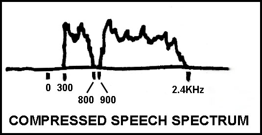
Frequency Compansion
By manipulating the FFT frequency band data, DSP can be used to shift frequency bands. This can be used to reduce analog bandwidth needed for intelligible speech.
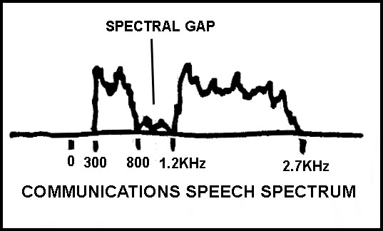
In speech, there is a frequency range where relatively little energy exists, around 800 to 1200 Hz. DSP can leave 300 to 800 Hz alone, but shift 1200 to 2700 Hz down to 900 to 2400 Hz, leaving a 100 Hz guard band between 800 and 900 Hz. This reduces the 300 to 2700 Hz bandwidth (2.4 kHz) to 300 to 2400 Hz (2.1 kHz), saving 300 Hz in transmission bandwidth.
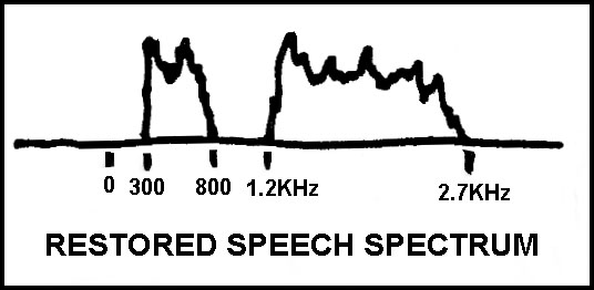
At the receiver, the 900 to 2400 Hz range is shifted back to 1200 to 2700 Hz. The 2.1 kHz bandwidth can squeeze into spaces where 2.4 kHz could not, the throughput audio is not as muffled as 2.1 kHz bandwidth audio would be, and no interference is heard in the 800-1200 Hz range.
DSP in Digital Modulation Systems
In digital modulation systems, the information being sent consists only of certain specific values or states, instead of the infinite number of possible values in the analog approach. The receiver has only to decide which state was sent. Interfering noises have no effect at all, unless they are strong enough to cause an incorrect modulation state decision. The greater the difference between the modulation states, the easier the decision task becomes. For example, in a two- state system, the receiver only has to decide whether the signal is in state one, or state two. An easier decision allows more noise to be tolerated.
Coherent Reception
If you know exactly when to look for a signal and what to look for, you are more likely to see it. For example, if the timings of a Morse CW signal can be anticipated, your receiver can synchronize to the specific periods when the CW signal is making its statement, and it can make the most of what it receives.
Standard Morse timing is one time period for a "dit," three time periods for a "dah," one time period for the space between a dit and a dah, and three time periods for the space between letters. These timings can be anticipated at the receiver, and better use can be made of the jumble of signal and noise that is received. By careful examination and analysis of the actual signal received during the known time slots, the receiver can better determine exactly what was sent.

Processor controlled systems can intelligently synchronize to incoming signals and make good use of coherence. Multiple timing possibilities can be simultaneously examined while acquiring sync, providing faster lock times. Data received during acquisition can be decoded after the fact once the true timing is determined, reducing or eliminating the need for sync-preamble headers. Appropriate frequency control and signal filtering can be applied automatically according to complex parameters.
Error Correction
Noise and interference occasionally cause errors in every communications system. Further improvement is possible using some form of redundancy. This gives the receiver a way to test incoming data for accuracy.
As a simple example, the message could be sent twice. If the two received messages do not match, some error or errors must have occurred. But then, which message was right? Or were they both wrong?
Modern error correction is done digitally and uses data mapping redundancy that can indicate a data error and also point to its location (or locations in the case of multiple errors). More redundancy tends to permit detection and correction of more errors, but also increases the amount of data that needs to be sent. This in turn reduces the information throughput, or requires higher speeds which call for wider transmission bandwidth or more signal states in the modulation system, which in turn decreases resistance to noise, which results in more errors to correct.
It might seem that error correction is self-defeating, but that is not true. In most cases, the worst noises are erratic in nature, tending to come in bursts. Modern error correction is very effective against burst noise.
There are several popular error correction methods available. Reed-Solomon, BCH, Viterbi, and Golay are widely used. These techniques can correct significant error rates, and can be configured for various balances between redundancy overhead and error rate protection.
Generally these are based on the idea of a redundancy code. A block of data is examined bit by bit, and an redundancy code is generated in some convoluting process, usually a cyclic redundancy code (CRC), although a lookup table can be used. The data block and the redundancy code are then transmitted.
A duplicate convoluting process is performed on the received data block at the receiver, and the result should match the received redundancy code. If an error exists in the data, the received redundancy code will differ from the calculated redundancy code derived from the received data block. The bit pattern of this difference is called the "error syndrome." In a properly designed system, every possible pattern of bit errors in the received data block (up to a certain maximum number of total bit errors) produces a unique error syndrome. The relationship of the error syndromes to the bit error patterns is known, and this allows the receiving processor to trace the error syndrome back to the bit errors that caused it. Depending on the level of redundancy and the particular code used, this process can identify several simultaneous bit errors, which can then be corrected. There are a few variations on the exact processing scheme used to evaluate the incoming block, but one way or another an error syndrome identifies the errors, and the offending bits are inverted to get correct data.
But only about three wrong bits out of 24 can be corrected. For a doubling of necessary data flow, we can only tolerate three bit errors in any 24 bit (12 data and 12 redundancy) data word. How could we handle a 300 ms static crash that could damage hundreds of bits?
Interleaving
To keep a long burst error from contaminating more than a few bits here and there, we shuffle the bits around in the message. Usually we stack data words (including redundancy bits) in rows, and read it all out by columns. Then we transmit this shuffled data. At the receiver, we do the reverse; we write the data in columns, and read it out by rows.
Even if a noise burst interferes with many consecutive bits, the corrupted bits are spread out to only a few here and there when the receiving system unshuffles the data. Usually the bit errors are scattered enough that the maximum error rate is not exceeded. Then the error syndrome is examined, the bit errors are identified and corrected, and clean data is received.
Interleaving averages out the error rate over several data blocks. When the errors are spread out in this way, they can usually be corrected unless the burst error is too long or the average error rate is too high.
But even with interleaving, sometimes the error correction system will be overwhelmed. In that case the loss is accepted, or the receiver requests a retransmission of the defective blocks.
Interleaving improves the burst error situation but introduces throughput latency. We must wait for the columns to be filled up before we can read the rows. Longer burst error tolerance requires longer latency because the tolerable burst error time can only be a fairly small fraction of the data block time.
Weak-Signal Reception
We all know how noise and interference degrade our ability to determine whether a signal is present, and how the signal is modulated. Most of us know that narrower selectivity helps us receive weak signals by blocking out more interference. Some of us have discovered that extreme selectivity causes a blurring of modulation, requiring slower transmission speeds than could otherwise be used.
This process can be taken to any extreme. Modern digital receiving techniques can reduce effective receive bandwidth to a fraction of a Hertz. This is often done using the Fourier Transform method on a DSP or a computer. The Fourier analysis separates the incoming signal into many narrow frequency bands, whose energy levels can be measured and displayed as light levels in a scrolling display. Weak carrier signals can be clearly seen as a streak on this spectral display.
Super narrow-band receiving systems essentially examine signal statistics, and over a period of time a pattern emerges. But it takes time for the receiver to gather this statistical pattern. This is called "integration time". So any modulation of the signal has to be very slow, or the receiver will not recognize it. The best results are achieved with coherent detection, where integrations are synchronized with the data bit timing of the incoming signal.
In super-narrow-band systems, the receiver and transmitter need unusual frequency accuracy and stability. An error of 2 Hz can put the received signal completely off of a spectral display screen, and it may take several minutes to see that no spectral trace is visible. Frequency instability makes weak-signal slow PSK detection impossible, because carrier phase sync can not be maintained during periods of signal loss.
Some experiments have used Morse code that is so slow that it takes hours to send a station call sign. The slow CW appears as a dotted line on a spectrogram, and can be read by eye. The occasional amateur IDs at 10 or 20 WPM are far too fast to pass through the narrow band receive filter. The receiver only sees a slight reduction in signal as a result of the IDs, so slight that it is usually not even visible in the noise-induced variations.
Diversity
If we can receive the signal from two or more places, one of them might be able to receive it even when others can not. In addition to that, we can carefully combine all receiver outputs into one composite, which can produce a directional pattern optimized for a desired direction, or to minimize pickup of offending signals from other directions. We can also transmit and receive simultaneously on several frequencies. DSP can apply complex procedures to make the best use of diversity reception.
Spread Spectrum Communication
Earlier systems shared spectrum by using frequency separation and geographical separation. Where frequencies had to be shared within one geographic area, time sharing was used (wait until the other user is finished). Simultaneous use of the same spectrum in the same area was not practical. But wideband digital modulation techniques have changed this situation.
In spread spectrum designs, bandwidth is deliberately increased by sequential changes in center frequency (frequency hopping spread spectrum, FHSS), or by transmitting a high-speed code, and modulating that code (direct sequence spread spectrum, DSSS). Systems can have individual stations that take turns transmitting data at very high speed on a single center frequency (time-division multiple access, TDMA). Or, the individual stations can transmit on certain common center frequencies and yet be received separately because of differences in their high speed codes (code-division multiple access, CDMA). Combinations of these techniques are also possible.
Interference between stations and systems of this type which share the same or overlapping frequency bandwidths is controlled by exploiting differences between the hopping patterns and the coding of the signals. DSP looks for subtle changes in the combined signals at specific timings consistent with the known parameters of the transmitting stations. These patterns of subtle changes repeat many times during a data bit time, allowing clear determination of bit status even though many (if not all) of the measurements were corrupted to some extent by noise and interference. Knowing the bit status of the various signals, DSP can simultaneously decode the received signals. At the same time, DSP can evaluate the contribution of each individual signal and subtract them from the combination, effectively ignoring all known signals, to search for new signals.
Digital Data Compression
Digital processing is used to compress data files, speech and video data to reduce storage requirements and transmission time and/or bandwidth.
Data file compression is well known, usually based on the idea of a short notation for repeated character sequences (example: LZW coding), and/or shorter binary strings to represent more frequently used characters (example: Huffman coding).
Digital audio compression is used in sound work from communications to certain musical recordings. Digital systems analyze the spectral qualities of sounds and encode them for more efficient storage and transmission. Advanced systems dynamically assign different levels of importance to various frequency ranges according to their importance to communication or sound quality at each instant, assigning more of the available data bits to the most critical sound qualities and fewer of the bits to less important qualities. Fewer data bits then need to be stored or sent over the air, reducing the necessary signal bandwidth and storage requirements. This technology has made digital PCS telephones and digital audio tape recording possible.
Digital video compression examines shapes and qualities of images to encode them more efficiently. Many general qualities of images can be specified in very compact notation, allowing these systems to concentrate available bandwidth on moment-to-moment changes. These changes can also be noted compactly. (For example, instead of rewriting the entire picture, which hardly changed, thirty times per second, the system can report "Object 12553 moved 6 pixels to the right, eclipsing the background pixels to the right, and the following pixels on the left side changed as follows..."). This technology has made small-dish satellite TV and narrow-band digital high-definition TV possible.
______________________________
SPECTROGRAM, by R. S. Horne, is available for free download from the Spectrogram web page, www.monumental.com/rshorne/gram.html .
"RADIOGRAM", also by R. S. Horne, may also be available for free download on the Spectrogram web page, but if not it is available for free download from home4.swipnet.se/~w-41522/,
thanks to Johan Bodin, SM6LKM.
RETURN TO LF PAGE