|
Circuit Archives
Sensors & Transducers/ Flow
|
|
Low Flow-Rate Thermal Flowmeter
Reprinted with permission
from Rudolf Graf.
For this and over 1000 other electronic circuits, review and order Rudolf
Graf's Encyclopedia of Electronic Circuits on CD-ROM Vol-1
McGraw-Hill ISBN0078528119


FC33-1
|
Description:
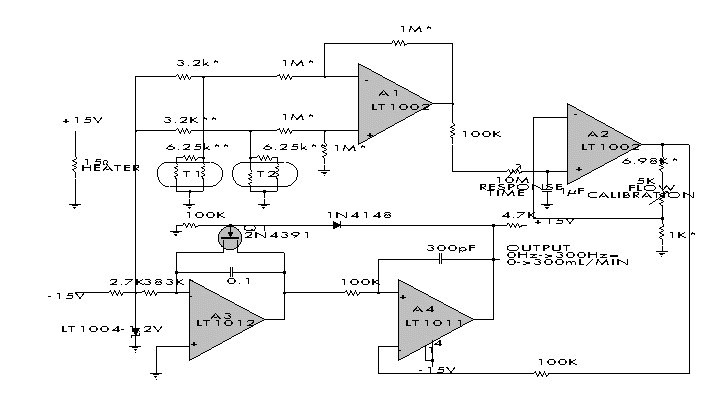
This design measures
the differential temperature between two sensors. Sensor T1, located before the heater
resistor, assumes the fluid's temperature before it is heated by the resistor. Sensor T2
picks up the temperature rise induced into the fluid by the resistor's heating. The
sensor's difference signal appears at A1's output. A2 amplifies this difference with a
time constant set by the 10 M adjustment. Fig. 33-1c shows A2's output versus flow rate.
The function has an inverse relationship. A3 and A4 linearize this relationship, while
simultaneously providing a frequency output. A3 functions as an integrator that is biased
from the LT1004 and the 338-K input resistor. Its output is compared to A2's output at A4.
Large inputs from A2 force the integrator to run for a long time before A4 can increase,
turning on Q1 and resetting A3. For small inputs from A2, A3 does not have to integrate
long before resetting action occurs. Thus, the configuration oscillates at a frequency
which is inversely proportional to A2's output voltage. Since, this voltage is inversely
related to flow rate, the oscillation frequency linearly corresponds to flow rate. (Linear
Technology Corp., Linear Applications Handbook, 1987, p. AN5-5.) From figure FC33-1 from Encyclopedia of Electronic
Circuits Vol. 1.
|
|

