IEEE Transactions on Ultrasonics, Ferroelectrics, and Frequency Control, vol. 43 no. 5, pp. 818-831, September 1996.
© 1996 IEEE. Personal use of this material is permitted. However, permission to reprint/republish this material for advertising or promotional purposes or for creating new collective works for resale or redistribution to servers or lists, or to reuse any copyrighted component of this work in other works must be obtained from the IEEE.
ABSTRACT
The magnetic sensitivity of quartz crystal resonators is a consequence
of the ferromagnetic properties of the metal used as support for
the vibrating plate. Various magneto-mechanic interactions can
contribute to the overall sensitivity, the most important of which
is shown to be the change in Young's modulus of the spring material
submitted to a magnetic field, which in turn modifies the stress
in the quartz plate and then induces a change in the crystal resonant
frequency. The experimental setup and procedure are described
and a large number of experimental results obtained with resonators
of different technologies are presented and discussed. A comparison
between the magnetic behavior of identical resonators mounted
with different materials definitely proves the responsibility
of the supports in the magnetic sensitivity of resonators and
gives interesting information on its reduction.
As the oscillator performance increases, new applications such
as precision orbit determination need more and more accurate devices.
In fact, the measurement accuracy of the positioning systems using
the Doppler effect strongly depends on the frequency stability
of the master oscillator. As an example, the DORIS mission, whose
goal is to locate a satellite with a precision of 10 cm, requires
a frequency stability of the on-board oscillator of 5.10-13
[1]. It is well known that most of the frequency instabilities
are due to temperature variation, acceleration or ionizing radiation.
Many efforts have been made to improve oscillator performance
either by using selected components insensitive to the environmental
variations or by shielding the oscillator against these variations.
For the past few years, attention has been focused on magnetic
field effects, because it was observed that starting or stopping
on-board magnetic stabilizing equipment may lead to a slight frequency
shift in a nearby oscillator. The order of magnitude of this oscillator
magnetic sensitivity, which is about 10-11/G does not
permit the stability specification to be fulfilled. A number of
studies have been undertaken to identify the origin of the oscillator
magnetic sensitivity [2]-[4]. The studies have shown that almost
all components of the oscillator circuitry may have a more or
less important effect [5]-[7]. Of course, among the studied components,
the quartz resonator has been given special attention because
of its major role in the oscillator. From the experimental point
of view, the magnetic sensitivity is easy to see on the oscillator
as a whole but it is more difficult to measure the contribution
of the individual components since they have to be kept in the
magnetic field far from the other parts of the oscillator. To
increase the signal to noise ratio, the magnetic field used in
the experiment lies typically in the range of ± 40 G (±4
mT) which is larger than the actual value the oscillators typically
experience which is in the range ±10 G (±1 mT).
A. Resonators
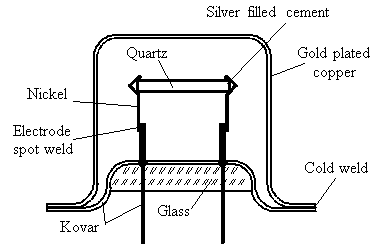
Most of the tested resonators are regular commercially available units in the range 5 to 10 MHz, fifth or third overtone, AT or SC cut operating in the low shear mode (C-mode). The internal assembly of one of these resonators in shown in Fig. 1, the quartz disc is held by two nickel springs soldered on two kovar supports. This latter material is used because it has the same thermal expansion coefficient as the insulating glass through which the supports pass. The electrical connection between quartz electrodes and springs is provided with a conducting silver-filled cement. The resonator is maintained under vacuum by a gold-plated copper cap cold-welded to a kovar base. In most cases, electrodes were made of a 700-Å gold layer deposited on a 20-Å chrome underlayer. In some samples, electrodes were also made of aluminum.

B. Magnetic Field Production and Measurement
Preliminary experiments [8] have shown that the magnetic sensitivity of oscillators and resonators strongly depends on the orientation of the magnetic field. Furthermore, it is highly desirable that the device under test keeps the same position in all experiments so as to avoid errors due to the earth's magnetic field or to gravitational effects when rotating the device rather than the magnetic field [9]. To this end, in all experiments, the resonator was held in a fixed position, the symmetry axis being always vertical (see Fig. 2).
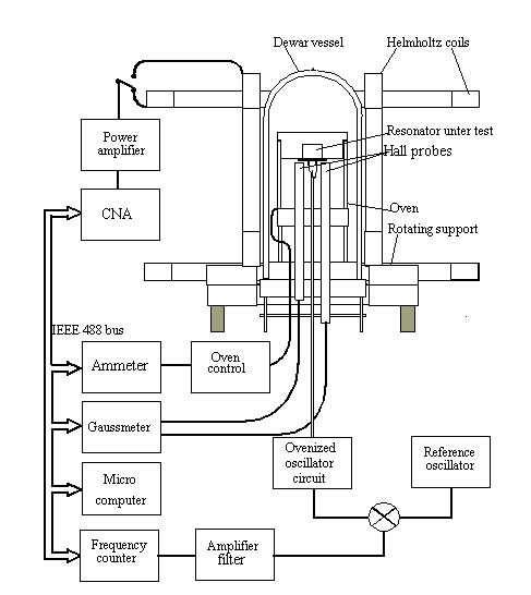
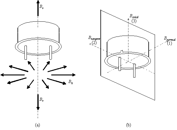
In order to give the magnetic field vector different orientations with respect to the resonator, the magnetic field is produced by using two pairs of Helmholtz coils. One of them is fixed to produce a vertical magnetic field along the symmetry axis of the resonator, the other pair can go around the symmetry axis thus enabling any radial orientation of the magnetic field in a plane normal to the symmetry axis (see Fig. 3). The origin for the radial orientation is arbitrarily set to zero when the magnetic field is normal to the plane containing the two supports. Measurement of the magnetic field nonuniformity shows that it is below the resolution of the gaussmeter in the relevant area i.e. less than 0.15 G in a volume 10x10x10 cm3. The magnetic field gradient can thus be estimated to be less than 1.5 G/m (0.15 mT/m) for a nominal magnetic field of 20 G (2 mT). In all the experiments, the most important source of perturbation comes from the temperature effects. To reduce these effects, the resonator under test is kept at its turnover point, in an oven placed in a Dewar flask.
To assess the temperature stability of the measurement setup, one of the resonators to be tested were operated in the B-mode, so that it acted as a temperature sensor with sensitivity -33 ppm/°C. Several measurements have shown that, when the temperature equilibrium is reached, the temperature stability of the oven is better than 10-4°C over the experimental duration; that is, about 100 s. If it is assumed that the temperature is not exactly set at the turnover point when operating in the C-mode, resulting in a residual temperature sensitivity about 2.10-7/°C, the overall relative frequency fluctuation induced by the temperature variation remains within 2.10-11. This is one or two orders of magnitude below the magnetic effect.
The oscillator circuit is kept in a separate oven far from the
magnetic field so as to avoid unwanted magnetic effects on the
other parts of the oscillator. Nevertheless, temperature effects
and other environmental perturbations can still affect the measurement
through the rigid coaxial cable needed to connect the resonator
to the oscillator circuit. In order to improve the signal to noise
ratio, the magnetic field is given a low frequency sinusoidal
modulation enabling the use of the signal processing method described
below. The driving current in the coils coming from a low frequency
generator through a power amplifier provided a magnetic field
in the range ±40 G (±4 mT). It is measured by means
of a gaussmeter using two Hall effect probes located near the
resonator, one probe for axial field measurement and the other
one for radial field measurement.
C. Magnetic Sensitivity Measurement and Data Processing
In most cases, the overall frequency shift observed lies in the range 10-9 when the resonator is submitted to the magnetic field previously described. The measurement of such small variations is performed by using the popular method represented in Fig. 4.
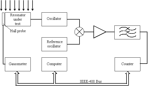
The frequency of the oscillator under test is compared with a reference oscillator by using a balanced mixer, a low noise amplifier and a low pass filter. The beat frequency reproducing the oscillator frequency variation is usually in the range from a few tens to a few hundred hertz and can thus be measured with an enhanced resolution by means of a frequency counter. This frequency variation as well as the magnetic field are simultaneously sampled and stored as a function of time in a microcomputer. The entire experiment is automated by using an IEEE-488 bus interface. The period of the low magnetic field excitation has been chosen to meet two opposing requirements: it has to be long enough to insure that no dynamic magnetic effects can occur and short enough to avoid long-term temperature drift, which could affect the accuracy of the data processing. Some preliminary experiments performed in various conditions have shown that an excitation period of 100 s and a sampling time of 1 s constitute a satisfactory compromise. In the actual experimental setup, relative frequency variations of a few parts in 1012 can be seen with a reasonable reproducibility.
Because of the periodic character of the magnetic field excitation and the resonator frequency response, it is possible to average the data over a number of periods (usually several tens). In fact, it is well known that in such a case, the signal-to-noise ratio increases as the square root of the cycle number. In addition, the low-frequency variations due to the temperature drift can be partially removed by performing a first-order regression on each period of the excitation signal. Fig. 5 demonstrates the effect of this data processing. Fig. 5(a) and (b) shows the frequency versus time and the frequency versus magnetic field raw data, and Fig. 5(c) shows the result obtained after the averaging and regression processes have been performed. As shown in Fig. 5(c), the data processing also corrects for the sign reversal due to a reference frequency higher than the measured frequency (see Fig. 4).
In most cases, the magnetic sensitivity is measured in the three main directions shown in Fig. 3(b). Fig. 6 shows a typical example of the results thus obtained. It should be noted that the records are quite reproducible, as demonstrated by Figs. 6(c) and 7, which show two different records performed on the same resonator with the same magnetic field orientation. In these figures, the origin of the vertical axis, arbitrarily chosen, has no particular significance.
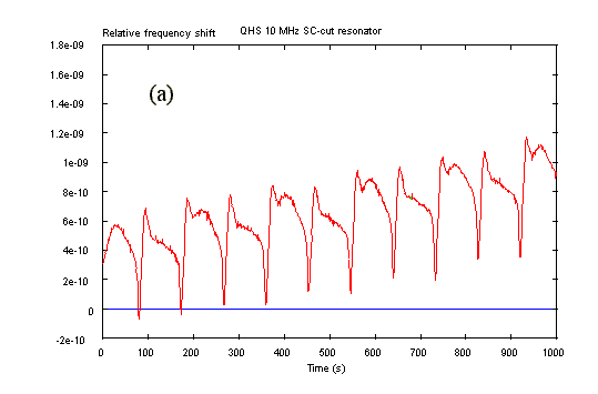
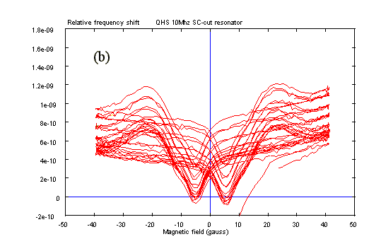
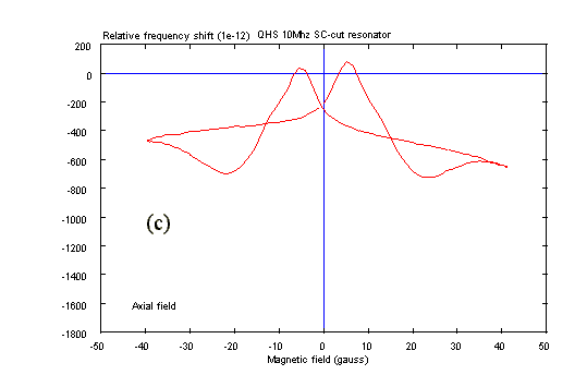
Figure 5. (a) Raw data frequency shift versus time. (b) Raw data
frequency shift versus magnetic field. (c) Averaged result with
drift and sign corrections.
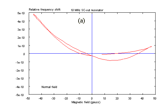
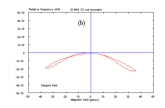
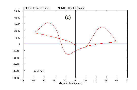
Figure 6. Magnetic sensitivity of a regular resonator with magnetic
field: (a) normal to the support plane, (b) in the support plane,
and (c) along the symmetry axis.
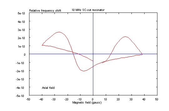
Figure 7. Another record performed on the same resonator as in
Fig. 6(c) demonstrates the reproducibility of the phenomenon.
A. Orientation
On some samples, the magnetic sensitivity curve is not symmetrical with respect to the vertical axis as it should be in regard to the geometrical symmetry of the resonator arrangement. Sometimes, this effect is due to a misalignement of the sample with respect to the magnetic field as demonstrated in Fig. 8, nevertheless, in many cases the asymmetry of the curve does not depend on the orientation of the resonator and could reveal in fact an asymmetry in the internal assembly of the device; this point will be further discussed later.
Fig. 9 shows the records obtained when the magnetic field is rotated around the symmetry axis of the resonator. In this case, the maximal sensitivity is observed when the magnetic field lies in the support plane (90° or 270°).
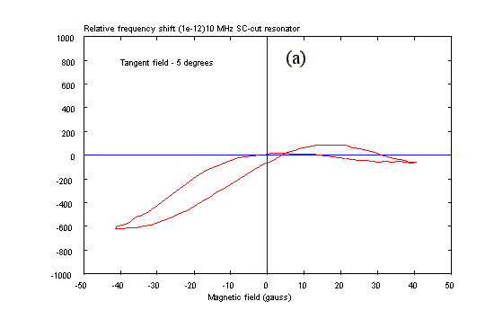
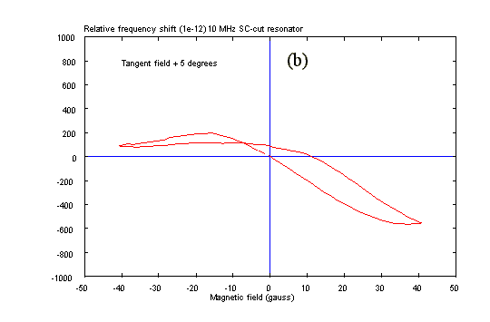
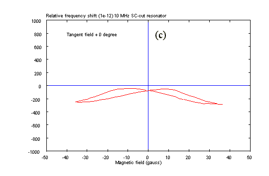
Figure 8. Effect of a slight rotation around the symmetry axis
of the resonator.
(a) Tangent field -5°. (b) Tangent field +5°. (c) Tangent
field +0°.
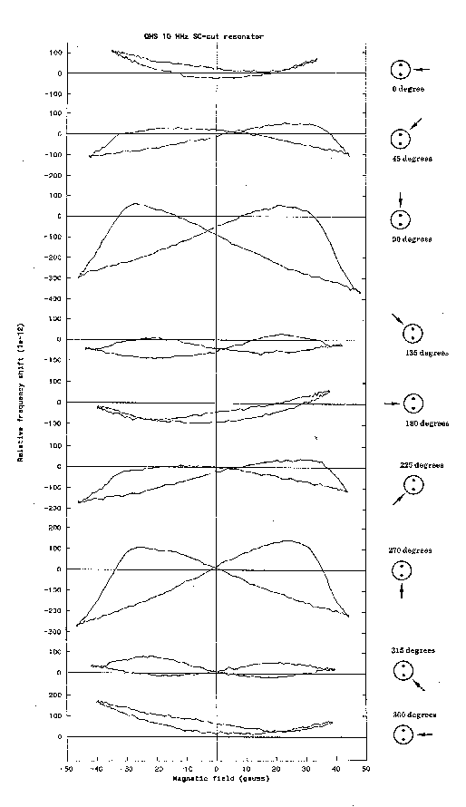
Figure 9. Magnetic sensitivity obtained when rotating the magnetic
field around the symmetry axis of the resonator.
B. Magnetic Field Strength
The amplitude of the magnetic field used in the experiments has
been chosen so as to obtain a sufficient signal-to-noise ratio.
Nevertheless, the shape and the amplitude of the magnetic sensitivity
"signature" of a resonator strongly depend on
the strength of the applied magnetic field, as seen in Fig. 10;
it represents the records obtained on the same resonator with
smaller and smaller magnetic field amplitude. Note that the low
level behavior noticeably differs from the higher level behavior,
so that it is dangerous to extrapolate the low level sensitivity
from a high level measurement. As an consequence, the magnetic
sensitivity of a resonator, or any other component as well, should
never be given without specifying the magnetic field amplitude
used for the measurement. Recommendations for the operating procedure
to be used for magnetic sensitivity measurement are currently
being plublished [10].
C. Magnetic Field Offset
Fig. 11(a) shows the magnetic sensitivity of a QHS 10-MHz SC-cut
resonator while fig. 11(b) shows the results obtained on the same
resonator when giving the magnetic field a dc offset of, respectively,
-10, 0 and +10 G superimposed on the main slowly varying magnetic
field. As expected, the magnetic signature strongly depends on
the magnetic polarization of the material. In addition, when comparing
Fig. 11(a) and (b) it can be observed that the shifted magnetic
signature in Fig. 11(b) approximately follows the corresponding
part of the main cycle in Fig. 11(a).
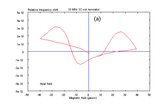
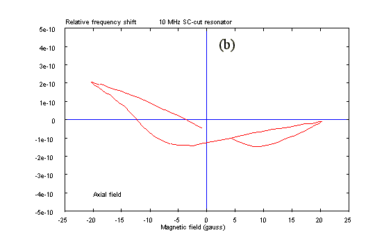
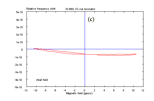
Figure 10. Magnetic sensitivity curves obtained with smaller and
smaller magnetic field amplitude. (a) Amplitude ±40 G (±4
mT). (b) Amplitude ±20 G (±2 mT). (c) Amplitude ±10
G (±1 mT).
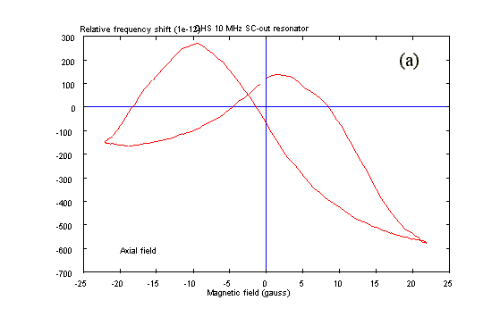
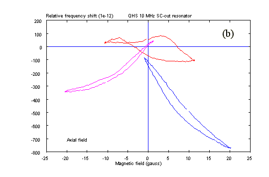
Figure 11. Influence of a dc magnetic field offset on the magnetic
sensitivity of a QHS 10-MHz SC-cut resonator. (a) Amplitude ±20
G (±2 mT) without offset. (b) Amplitude ±10 G (±1
mT) with offset -10 G, 0, +10 G.
D. Temperature
Magnetic sensitivity of a resonator measured at various temperatures
within the range 60-80°C (Fig. 12) shows that the overall
amplitude of the curve slightly decreases when the temperature
increases (about 8% for 20°C). The shape of the signature
remains practically unchanged. Due to the weakness of this effect
it has not been further investigated.
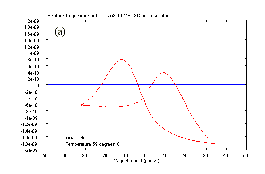
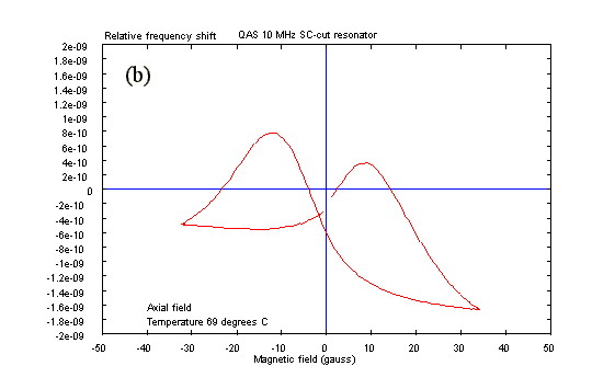
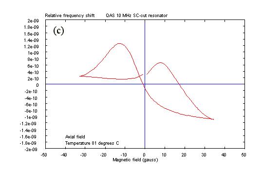
Figure 12. Influence of the temperature on the resonator magnetic
sensitivity. (a) Temperature 59°C. (b) Temperature 69°C.
(c) Temperature 81°C.
More than 20 resonators of various cut, frequency, support material
and/or enclosure have been measured in the three main directions
[Fig. 3(b)]. Only a selected number of results will be reported
here.
A. QHS Technology
The name used by the manufacturer (THOMSON-CEPE, F-95105 Argenteuil Cedex) is used to designate the regular resonators. The results shown in Fig. 13 have been obtained with 10-MHz third-overtone SC-cut resonator using nickel springs in T2111 box enclosure (MIL HC40/U). Only the results obtained in the most sensitive direction, along the symmetry axis, are shown.
Figs. 13(a) and (b) show the results obtained with two QHS resonators from the same batch, and Fig. 13(c) is obtained with another resonator of same technology from another batch. The most surprising fact when looking at these results is the great variety of "magnetic signature," while the overall amplitude keeps approximately the same order of magnitude.
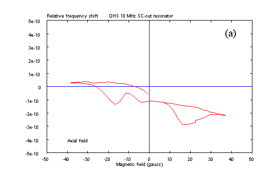
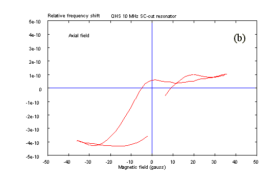
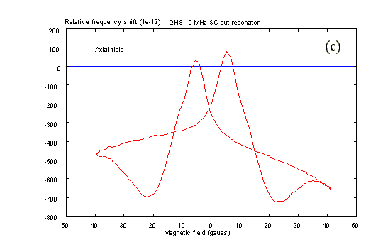
Figure 13. Magnetic sensitivity of QHS 10-MHz SC-cut resonators.
(a) Batch 9125 sample 1/015/09. (b) Batch 9125 sample 1/015/10.
(c) Batch 9122 sample 1/792/15.
B. QAS Technology
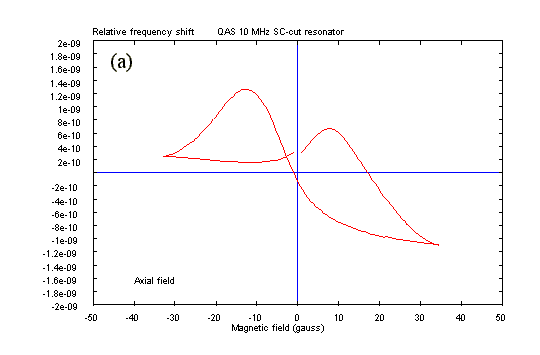
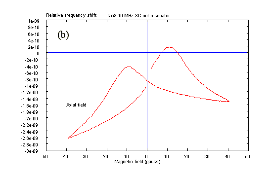
Figure 14. Magnetic sensitivity of QAS 10-MHz SC-cut resonators. (a) Batch 9137 sample 1/096/04. (b) Batch 9137 sample 1/096/12.
These resonators differ from the previous resonators by the fact the vibrating part of the crystal plate is sustained by small quartz bridges connected to a concentric quartz ring supported by nickel springs. This arrangement intends to isolate the vibrating part of the plate from the support stresses. Figs. 14(a) and (b) are obtained with two QAS from the same batch. Their magnetic signatures are fairly similar but much larger than those of QHS (the scale in Fig. 14 is four times larger than the scale of Fig. 13).
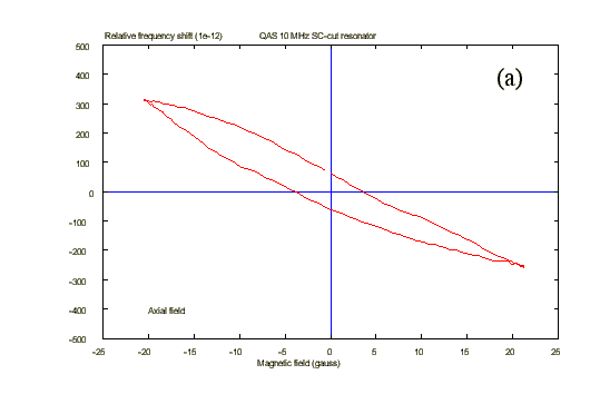
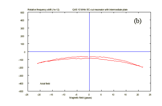
Figure 15. Magnetic sensitivity of QAS 10-MHz SC-cut resonators: (a) without intermediate plate and (b) with intermediate plate.
Another experiment has been performed to compare the results obtained
with two QAS resonators. One of resonators [Fig. 15(a)] is a regular
one, the other resonator is mounted on an intermediate plate [Fig.
15(b)]. The barometric sensitivity of the first resonator has
been measured to be 25 times larger than the second, while its
overall magnetic sensitivity is six times larger. It will be shown
in the next section that the magnetic sensitivity of the resonator
comes from the ferromagnetic properties of the spring material.
The most probable magneto-elastic mechanisms involved in the resonator
sensitivity are even functions in the applied magnetic field and
the frequency shift versus magnetic field curves would present
the same symmetry and should be also even functions in the magnetic
field. This is almost true in a number of figures presented in
this paper, but this is not always the case [see, for example,
Figs. 13(b) and 15(a)]. It is highly probable that the asymmetry
of the magnetic sensitivity curves reveals in fact an asymmetry
in the mechanical mounting of the quartz plate. As a consequence,
the stress induced in the plate by the magneto-elastic effects
in the springs is no longer symmetrical with respect to the plate
axis, and the resulting frequency shift loses the initial symmetry
of the phenomenom. Hence the high barometric sensitivity of the
resonator used for Fig. 15(a) could be explained by a mounting
asymmetry revealed by the strong asymmetry of the magnetic sensitivity
curve. Indeed, it is well known that any asymmetry in the mechanical
assembly of a resonator drastically increases its sensitivity
to environmental perturbations (acceleration, pressure, etc.)
[11].
C. BVA Resonators
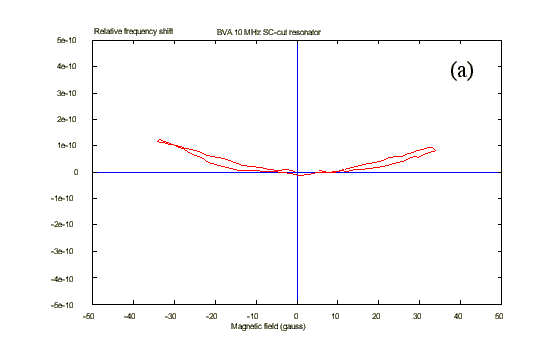
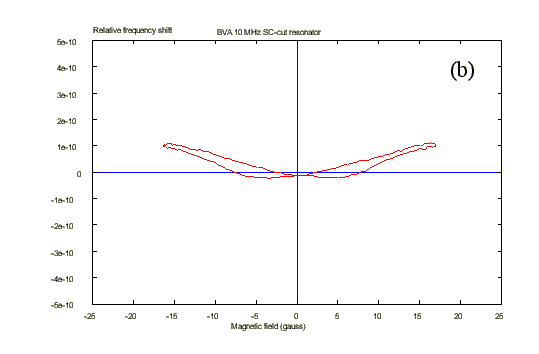
Figure 16. Magnetic sensitivity of two BVA 10-MHz SC-cut resonators. (a) Sample 17/02. (b) Sample 27/07.
As in the QAS resonator, the vibrating part of the crystal plate
of a BVA resonator is connected to a concentric ring by quartz
bridges. In addition, the ring is gripped between two adjacent
quartz plates which support the electrodes which are then not
directly deposited on the active part of the vibrating plate [12].
This arrangement has proved to be much less sensitive to environmental
conditions than the regular resonators. Fig. 16 shows that this
is also true for the magnetic sensitivity.
D. Spring Material
The magnetic sensitivity of quartz resonators has been observed
for a long time and several explanations on its physical origin
have been given [2], [3], [13]. A few years ago we demonstrated
that this sensitivity comes from the ferromagnetic properties
of the plate supports [6]. This point will be further developped
in the next section. Since then, many efforts have been made to
reduce the magnetic sensitivity of the resonator, including testing
materials different from the nickel usually used. A set of five
resonators has been investigated. All of the resonators are identical,
except the mounting springs are made of different materials. The
resonators are all 6.144-MHz AT-cut QHS units. Because of the
particular frequency of these resonators the experimental conditions
have been slightly modified, the curves obtained, shown in Fig.
17, are then a bit more noisy, nevertheless they remain worth
reading. They are presented from the greatest to the least magnetic
sensitivity. The kovar appears to be much more sensitive than
the nickel while stainless steel is noticeably less sensitive.
It is not surprising that the resonator made with copper-alloy
springs does not exhibit any perceptible magnetic sensitivity.
This last experiment definitely proves the responsibility of the
magnetic properties of the springs for the magnetic sensitivity
of resonators. Of course, a reduced magnetic sensitivity is not
the only goal to reach, the resonators still have to keep their
performance in terms of mechanical behavior, accelerometric and
barometric sensitivity, aging, etc [14].
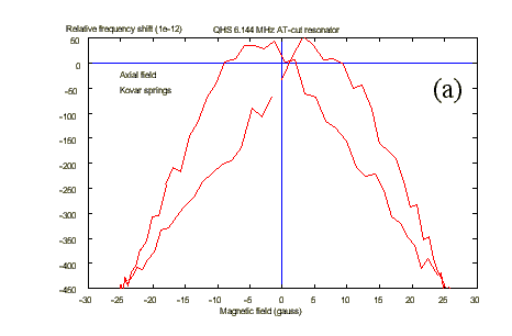
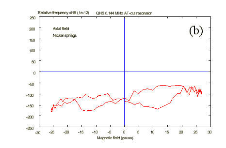
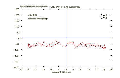
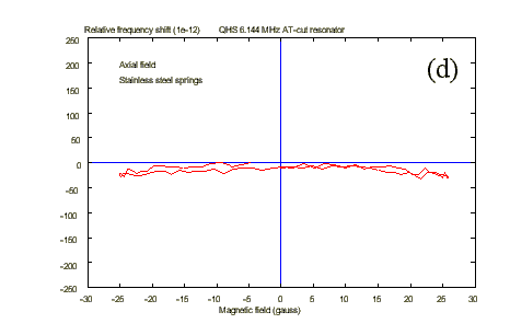
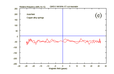
Figure 17. Magnetic sensitivity of QHS 6.144-MHz AT-cut resonators
made with different spring materials. (a) Kovar, (b) nickel, (c)
stainless steel, (d) stainless steel (other kind), and (e) copper
alloy.
Several effects could exist at the origin of the magnetic sensitivity of the quartz resonator. Nevertheless, many of them have such a weak influence that they cannot explain the observed sensitivity. For example, it is known that quartz is diamagnetic. Its magnetic susceptibility has been measured to be Xm = -0.46 10-6 [15]. When exposed to an inhomogeneous magnetic field, a diamagnetic material of volume tau experiences a force given by
directed in the decreasing magnetic field sense [16]. Assuming a linearly decreasing field 20 G (2 mT) with a maximum gradient of 0.15 mT/m, the resulting force would be 10-14 N. The stress induced by this force in the quartz plate and the resulting frequency change is not simple to calculate. Nevertheless, taking the worst-case estimate of a diametrical compression [17], the relative frequency shift induced by such a weak force would be in the 10-18 range.
Another magnetic effect concerns the change in the resonator motional resistance due to the eddy currents produced in the electrodes by their motion in the external magnetic field. An assessment of the frequency deviation due to this effect in a 20-G (2-mT) magnetic field for an AT-cut with 1-mm Cu electrodes gives an effect in the 10-22 range [13].
Magnetostriction of the electrodes when they are made of ferromagnetic material has also been considered but, once again, the order of magnitude is in the 10-14 range for a 5-MHz AT-cut in a 20-G (2-mT) magnetic field [2].
In addition, magnetic sensitivity is observed even when the electrodes are made of nonferromagnetic material so that other magnetomechanical effects, such as the Delta-E effect of the electrodes, cannot explain the frequency deviation [3].
The only remaining source of magnetomechanical action is the ferromagnetic
nature of the springs used to hold the quartz plate. The various
mechanisms that can be considered to explain how a magnetic field
induces a mechanical action in a ferromagnetic material will be
briefly presented here [18].
A. Compass Effect
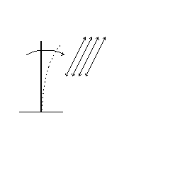
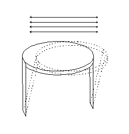
The first effect is explained by the fact that ferromagnetic materials are constituted of small magnetic domains initially randomly oriented. When submitted to a magnetic field, these domains tend to align along the direction corresponding to the easiest magnetization direction, which is usually the rolling direction of the material. As the domains reach the saturation state, their magnetization vectors oriented along the same direction are subject to a torque tending to align them with the external magnetic field, just like a compass needle. This situation is sketched in Fig. 18.
Since the supports of the quartz plate are clamped on the base, the assembly could bend as shown in Fig. 19, resulting in a maximum effect when the magnetic field lies in the plane of the supports.
It should be noted that a change in the magnetic field sense also
changes the sense of the magnetization vector so that the resulting
torque does not change.
B. Mutual Repulsion
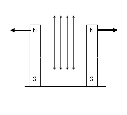
Two parallel ferromagnetic supports close together submitted to a magnetic field act as two small magnets of same polarity. As a consequence, they tend to repel each other and to induce a diametrical tension in the quartz plate they support (see Fig. 20).
As in the previous case, a change in the applied magnetic field sense also changes both magnet polarities so that the resulting effect is always a mutual repulsion.
C. Change of Elastic Modulus
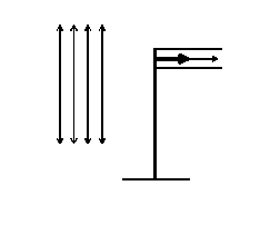
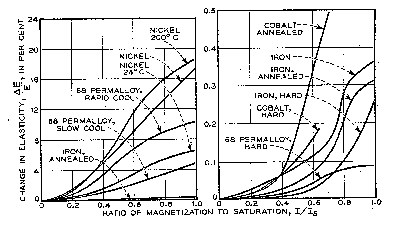
This effect, also called Delta-E effect, consists of a change in the Young's modulus of ferromagnetic materials when submitted to a magnetic field. As a result, the pressure exerted by a ferromagnetic spring on a sustained disc is modified by an external magnetic field (see Fig. 21). Fig. 22 shows the variation of Young's modulus for various ferromagnetic material [18]. The sign of this variation does not depend on the sense of the magnetic field.
D. Magnetostriction
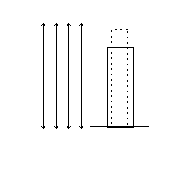
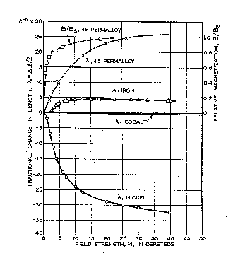
The last magneto-mechanic effect is the magnetostriction, which is a change in the dimensions of a ferromagnetic material submitted to a magnetic field. For example, as shown in Fig. 23, a rod of nickel submitted to a magnetic field undergoes a contraction in length and an expansion in the other directions so that the volume is kept approximately constant. In many cases, ferromagnetic materials may present an expansion in lengh rather that a contraction. In all cases, the deformation (contraction or expansion) only depends on the kind of material, but not on the sense of the applied magnetic field. Fig. 24 shows the magnetostriction coefficient of some ferromagnetic materials [18].
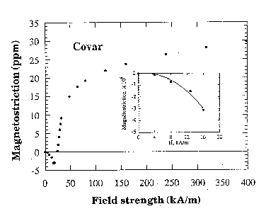
The kovar used in various parts of the resonator packaging (see Fig. 1) is also a ferromagnetic material, the magnetostriction of which has been measured at the Laboratoire de Magnétisme Louis Neel in Grenoble. The result is shown in Fig. 25 [19].
It is easy to understand that the magnetostriction of the springs and/or the supports can induce stress in the disc they sustain.
E. Hysteresis
Most of the magnetic effects described above do not depend on the sense of the applied magnetic field and present a maximal effect when the field is directed along the largest dimension of the material. Also, most of these magnetic effects present a more or less pronounced hysteresis depending on the kind of material. For example, Fig. 26 shows the hysteresis of magnetostriction in nickel [18]. It is interesting to note the similarity between the magnetostriction hysteresis curve (Fig. 26) and the resonator magnetic sensitivity shown in Fig. 14, for example.
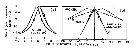
Figure 26. Hysteresis of the magnetostriction in nickel (after
[18]). (a) Well-annealed and (b) hard and partially annealed.
F. Discussion
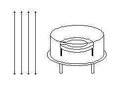
In almost all magnetic sensitivity measurements performed on resonators, the maximal effect is observed when the magnetic field is directed normal to the plane of the resonator plate [4] (see Fig. 27). This fact implies that the "compass effect" is probably not responsible for the observed sensitivity.
The order of magnitude of the repulsion forces between the two supports is not consistent with the stresses necessary to account for the observed resonator magnetic sensitivity, thus this effect should be also discarded.
For some time, the magnetostriction was considered as the most probable magnetoelastic effect responsible for the resonator magnetic sensitivity because of the similarity between the magnetic sensitivity curve of the resonator (Fig. 14) and the magnetostriction hysteresis curve of the spring material [20] (Fig. 26). Nevertheless, with regard to the geometry of the plate mounting (Fig. 1) only the lateral magnetostrictive expansion of the spring may induce stresses in the plate and the order of magnitude of this expansion (a few nm) is hardly consistent with the observed frequency variation. Thus the magnetostriction is probably not the most important cause of the resonator magnetic sensitivity.
The only remaining effect is the Young's modulus change. In fact,
when the quartz disc is mounted, it is gripped by the two nickel
springs so that the plate is prestressed by the supports, any
change in the Young's modulus of the springs will modify the diametrical
forces acting on the plate and then its resonant frequency. The
curve plotted in Fig. 22 shows that, the Young's modulus of nickel
may increase from about 6% up to 16% when the material reaches
its saturation state (a few tens of gauss). This order of magnitude
is fully consistent with the observed frequency changes.
The magnetic sensitivity of resonators comes undoubtedly from the ferromagnetic properties of the springs used to hold the quartz plate. This sensitivity can be drastically reduced by using copper alloy springs. Kovar and nickel should be avoided. Although the quartz plate itself is not responsible for the magnetic sensitivity, the magnitude of the phenomenon can be strongly increased by the geometrical characteristics of the disc; it is obvious that the thicker the plate the lower the sensitivity. Even in a same lot of resonators, a great variety of magnetic signatures is often observed, some of them being abnormally asymmetrical in view of the magnetic action and geometric assembly symmetries. It is highly probable that these anomalies betray a geometric asymmetry in the plate mounting. In most of the experiments, the higher sensitivity is observed when the magnetic field is directed along the resonator axis that is along the largest dimension of the springs.
Among the possible magnetoelastic effects responsible for the resonator magnetic sensitivity, the most important is probably the change in the Young's modulus of the spring material although, in some cases, the magnetostriction should not be entirely discarded.
It is highly probable that the complexity of the magnetic signature has to be attributed to the spring Young's modulus hysteresis rather than to a complicated stress and strain interaction between plate and springs. This interaction might be as simple as a diametrical tension or compression for which the induced frequency shift is well characterized. Then, the magnetic sensitivity of resonators could constitute an extremely sensitive tool for the experimental investigations on the mechanical actions exerted on the resonator plate. In fact, by knowing the magnetic behavior of the spring, it is possible to determine the kind of the actions the plate is submitted to and the device thus obtained can be easily used, for example, to experimentally determine the lowest sensitivity fastening points on the plate or to study new shapes of springs and supports.
These applications still need theoretical modeling of the magneto-elastic
behavior of the various materials and it is in these directions
that efforts are currently continuing.
This work was supported in part by CNES and CNRS under Contract 932 88 534 7400 and by Thomson-CEPE.
The author wishes to thank Dr. G. Marianneau for his help, as
well as Prof. R. J. Besson and the companies CEPE and QKP for
providing resonators.
[1] M. Brunet, "Doris precise orbit determination and location system performances of ultra stable oscillators", Proc. of the 6th European Frequency and Time Forum, 1992, p. 125.
[2] J.J. Gagnepain and J.G. Théobald, "Influence d'un champ magnétique sur la fréquence propre d'un résonateur à quartz", C.R. Académie des Sciences, Vol. 292, série II, p. 283, 1981.
[3] L. Neel, "Sur la variation, en fonction d'un champ magnétique appliqué, de la fréquence propre d'une lame de quartz, revêtue d'électrodes adhérentes de nickel", C. R. Académie des Sciences, Vol. 292, série II, p. 1171.
[4] R. Brendel and E. Robert, "Weak magnetic field sensitivity of quartz crystal oscillators", Proc. 6th European Frequency and Time Forum, 1992, p. 99.
[5] F. Deyzac, "Oscillateurs à quartz de bord en environnement sévère. Sensibilité magnétique", ONERA. Technical Report # 37/7132 PY, 1988.
[6] R. Brendel, C. El Hassani, M. Brunet, and E. Robert, "Influence of magnetic field on quartz crystal oscillators", Proc. 43rd Ann. Symp. on Freq. Control, 1989, p. 268.
[7] R. Brendel, C. El Hassani, P. Krux, and E. Robert, "Magnetic sensitivity of oscillator components", Proc. 5th Europ. Freq. and Time Forum, 1991, p. 390.
[8] E. Robert and M. Brunet, "Susceptibilité magnétique des oscillateurs à quartz spatiaux", CNES Technical Report CT/DRT/TIT/TF 88/354, 1988.
[9] R.L. Sydnor, R. Brendel, and W. Wiedemann, "IEEE Standards Project P1193 : Electric and Magnetic Fields and Effects", Proc. 46th Ann. Symp. on Freq. Control, 1992, p. 791.
[10] IEEE-SCC-27 Working Group, "Guide for Measurement of Environmental Sensitivities of Standard Frequency Generators", Proposition PAR-P1193, 1994.
[11] F. Deyzac, "Oscillateur à quartz ultrastables à finalités militaire et spatiale. Amélioration du comportement mécanique", ONERA. Technical Report # 8/3945 PY 1993.
[12] R. Besson, "A new electrodeless resonator design", Proc. of the 31st Ann. Symp. on Freq. Control, 1977, p. 147.
[13] A. Ballato, J.J. Lukaszek, and G.J. Iafrate, "Subtle effects in high stability vibrators", Proc. of the 34th Ann. Symp. on Freq. Control, 1980, p. 431.
[14] J.P. Michel, M. Zafrany, M. Candelier, J. Lamboley, L. Xavier, F.A. Kunhast, and M. Nassik, "Influence of Part Stability on Ageing of Quartz Crystals", Proc. of the 8th European Freq. and Time Forum, 1994, p. 832.
[15] K. Voigt and K. N. Gessel, Math. Phys. Kl. Gottingen : Wissen, 1907, p. 123.
[16] M. Rouault, Electricité, vol. 2, Paris: Masson, 1965, p. 355.
[17] S. Ballandras, "Sensitivity of BAW devices to radial in-plane stress distribution, comparison between analytical and finite element results", Proc. of the 5th European Freq. and Time Forum, 1991, p. 50.
[18] R.M. Bozorth, Ferromagnetism, 8th edition Princeton, NJ: Van Nostrand, 1964.
[19] A. Barlet and E. de Lacheisserie, "Analyse de l'aimantation et de la magnétostriction de quelques composants d'un résonateur à quartz, Technical Report, 1993, unpublished.
[20] R. Brendel, B. Cretin, and A. El Habti, "Origin and
measurement of quartz resonator magnetic sensitivity", Proc.
of the 8th European Freq. and Time Forum, 1994,
p. 260.