Introduction
This page is one part of our 7-page tutorial on resistivity
and IP basics. It defines basic terms and relations between resistivity,
voltages, currents and electrode configurations.
The electrical properties of the ground can be mapped with inductive
electromagnetic (EM) methods, or using galvanic methods. Resistivity and
induced polarization profiling are usually performed together. The most
common application is mineral exploration, but there is a growing interest
in these techniques for engineering and environmental applications.
Resistivity, Apparent Resistivity and Chargeability [top]

Resistivity is a bulk property of material describing
how well that material inhibits current flow. This is slightly different
from resistance, which is not a physical property. If we consider
current flowing through a unit cube of material, resistivity is defined
as the voltage measured across the unit cube's length (V/m) divided by
the current flowing through the unit cube's cross sectional area (I/m2).
This results in units of Ohm m2/m or Ohm-m.
Conductivity is the inverse of resistivity.
Apparent resistivity, Ra, is determined from
a 3D form of Ohm's law which takes into account the geometry of electrodes
by using a "geometric factor", k.
-
Ra = K*V/I. Ra is the ground's true
resistivity only when measurements are made over a uniform earth.
-
This form is necessary since usually, geophysicists only have access to
the surface, even though it is subsurface structure that is of interest.
-
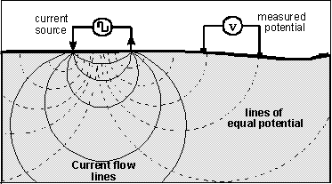
The pattern of current density in the ground is distorted by geological
layers or structures. Measurements detect the consequent distortions of
potentials.
Chargeability is a physical property that describes how well
materials tend to retain an electrical charge. There are more details on
why this phenomenon occurs later in the resistivity and
IP tutorial. Details of measurement and calculations for inversion
purposes are given in the general inversion
methodology tutorial.
-
When resistivity and chargeability are both required, static and
dynamic
voltages are measured.
-
Time-domain methods record decaying voltage after a DC transmitter
current is turned off.
-
Frequency and phase domain methods record the earth's response
to sinusoidal transmitter currents at different frequencies.
-
Just like resistivity, only an apparent chargeability can be calculated
directly from surface measurements. Rigorous inversion techniques are required
to estimate true distributions of intrinsic physical properties.
Chargeable ground has the ability to retain charge, rather like a capacitor.
If ground is chargeable, measured voltages will not follow exactly the
currents injected by the transmitter. If a steady current is suddenly shut
off, the voltage measured during the next few seconds will decay at a rate
dependant on the type of material. If a sinusoidal current is injected,
the resulting voltage will depend on the frequency. Chargeability can also
be estimated by recording the phase difference between transmitted current
and measured voltages. The phenomenon is also sometimes described as a
"complex resistance".
Common geological materials that are chargeable include disseminated
sulfides, clays, and graphite. There is also some evidence that variations
in electrolytes can affect bulk chargeability. Grain size appears to have
the strongest affect on chargeability, though there must also be conductive
particles within a porous medium filled with an electrolyte. The method
is most commonly used for mineral exploration, but it is becomming more
popular for environmental and engineering work
Voltages and currents [top]
Next we derive the simple relations between injected current, resulting
potential, and bulk resistivity.
-
We will make use of the 3D form of Ohm's law (remember volts = amps * resistance).
It is a constitutive relation used frequently in electromagnetics which
relates electric field strength, E, to current density, J,
in terms of resistivity.
 where Jr is current density in units of Ampers / metre2,
and rho is the resistivity defined above.
-
Recall from potentials theory that the potential (i.e voltage) at a point
that is a distance r from the current-source is just the work done
in going from infinity to the point r. That is,
 .
We can just plug in the expression above, but we need an expression for
current density in terms of parameters we control.
-
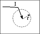
 If current,
I,
is injected into a uniform whole-space, then the current density through
a sphere that is a radius r from this point source of current, is
  .
.
-
Now we can find the voltage we would measure (using a volt metre with one
probe at infinite and the other on the surface at r) if a current
I
is injected as in the figure (the return electrode would be at infinite
too.) We can write
 .
.
-
If there is only a half space, this expression is halfed. Our geophysical
goal is to find out what the resistivity of the ground is, so for a uniform
half-space, using a point current source, the resistivity is
 .
This is very similar to the familiar Ohms-law, except there is a geometric
factor because we are working in three dimensions.
Common Arrays [top]
If there are two current electrodes, the potential is the superposition
of the effects from both. In a practical experiment, one electrode is the
positive side of a current source, and the other electrode is the negative
side. The current into each electrode is equal but of opposite in sign.
The potential measured is  ,
where the two r's are the distances from the measuring electrode
to the two current electrodes.
-
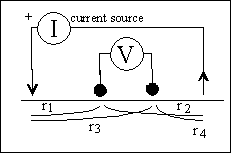
 Finally,
if the two potential electrodes are "close" to the source, the measured
voltage is
  ,
where distances are shown in the figure.
-
As an example, consider the Wenner array (alpha type),
in which all electrodes are separated by a metres. The distances
rn
are therefore r1 = a, r2 = 2a, r3 =
2a, r4 = a. Plugging these into the equation above gives
 .
In other words the geometric factor for a Wenner array is 2 pi a.
-
In general, we say that for any configuration of electrodes, resistivity
depends upon injected current and measured potential according to
 where K is the geometric factor. Here is a figure
that summarizes the most commonly used configurations, and lists their
geometric factors.
Performing Surveys [top]
-
 To measure the ground's
resistivity, current is applied directly into the ground using a pair of
electrodes.
-
Resulting potential differences (voltages) are measured directly using
two different electrodes, probably at several locations for each placement
of transmitter electrodes.
Types of resistivity surveys
-
Soundings provide a 1-D "geoelectric" section, or vertical structure
at one (surface) location. Electrode geometry is varied symmetrically about
a single measurement location. For more on sounding, see the comprehensive
notes on resistivity in the resistivity
section of the Introduction
to Geophysical Exploration web-based course hosted by the Colorado
School of Mines (supported in part by the Society
of Exploration Geophysicists).
-
Profiling provides information about lateral variations, usually
with some information about vertical variations.
-
The most common arrays for mineral exploration work are the dipole-dipole
and pole-dipole arrays, but others are used occasionally.
-
The most common configurations used for ground water and environmental
work are the Wenner (alpha) and Schulmberger arrays.
-
Wider electrode spacing results in deeper penetration.
-
Resistivity and induced polarization surveys can also be conducted from
within a borehole, but we will not pursue this aspect here.
The next task is to outline how raw resistivity or IP data are commonly
plotted - i.e. to introduce pseudosections.


 .
We can just plug in the expression above, but we need an expression for
current density in terms of parameters we control.
 If current,
I,
is injected into a uniform whole-space, then the current density through
a sphere that is a radius r from this point source of current, is
  .
. Finally,
if the two potential electrodes are "close" to the source, the measured
voltage is
  To measure the ground's
resistivity, current is applied directly into the ground using a pair of
electrodes.