Figure 1 - Basic Transistor Test Method

| Elliott Sound Products | Project 31 |
The design featured here is just what you need, and provides the ability to test:
There are a couple of photos of my unit at the end of this article, so you can get some idea of what it might look like when finished. Bear in mind that this tester is different from mine (it has more features), so don't try to make a direct comparison of the switching. Mine (unfortunately) does not have the separate base current and collector current range switches, and is somewhat less useful as a result. Maybe I'll have to make one of these next.
Warning
One caveat I must make at the outset.
Like any such commercial offering, this tester is just as capable of blowing
up a transistor as it is of testing it. It is entirely the responsibility
of the user to ensure that the settings are correct before pressing the
Gain switch. The author takes absolutely no responsibility for any
damage, whether direct or consequential that may be done to the device
under test or the operator due to the use or inability to use the project
described.
The final unit's range switching and other functional blocks are shown in Figure 2, and it can readily be seen that it is comprised almost entirely of switches and resistors. No printed circuit board is needed, since most of the resistors should be connected directly to the switches, or may be mounted on tag strips as I did in my original unit.

Figure 2 - The Function
Switching For The Tester
The meter range extends from the maximum meter sensitivity of 100uA in decade steps up to 1A. The highest range was limited to 5A deliberately - even at this current, the transistor will be dissipating up to 20 Watts worst case, so the device under test should be mounted on a heatsink, or the test should be kept to very short duration, otherwise the transistor will overheat and may (will) be destroyed or severely impaired.
Power Ratings Of Resistors
The power ratings for the various meter
shunt resistors are important. The 2 Ohm resistor (5A range) is best
made using two five 10 Ohm 10W resistors in parallel. The dissipation
will be a maximum of about 70 Watts, but will only be used for a short
time - otherwise the transistor will overheat and fail. Mount the
resistors on a section of heatsink with an aluminium bracket, making sure
that the bracket and heatsink make good thermal contact. Use some
thermal compound to make sure that as much heat as possible is removed.
Do not use the same heatsink as the power regulator. The added heat
from the resistors will raise the temperature too far, and will endanger
the life of the semiconductors.
The 10 Ohm resistor (1A range) should also be 10 Watts, but does not need a heatsink (although mounting it with the others will not hurt). You must keep it away from other components, because it will get very hot.
The 100 Ohm (100mA range) can be a 5 Watt unit, and will run quite cool (only 1.6W dissipation at worst), and all other resistors should be 1/2W types. Since absolute accuracy is not overly important, 5% tolerance is fine, but 1% can be used if you want to.
Switch Functions
The various switches are as follows:
Figure 3 - NPN / PNP
Switching
Figure 3 shows the switching for NPN and PNP (everything has to be reversed in polarity), as well as the meter and its calibration resistors and protection diodes. These will conduct when the voltage across the meter exceeds 0.65V, so if the same meter movement (or one passably similar) is used, a maximum overload current of 170uA is possible. Although this will cause the needle to swing hard against the stops, it will not damage the movement.
I have used an analogue meter movement because they are much simpler to implement, and are also somewhat cheaper than a digital panel meter. The latter needs a floating supply, and they are easily damaged by stray high voltages. The high voltage is used to test the breakdown voltage of the transistor, and will give a nasty bite, so I suggest that you treat it with great respect.
The meter movement is a standard 100uA unit, and I based the resistor values on the specified meter resistance of 3,900 Ohms. If the meter you use is different, then you must make some adjustment to the 82k and 15k resistors. The aim of these is to make the entire circuit have a resistance of 100k. Since 10V is developed across the shunt resistors for full scale, this means that 10V and 100k = 100uA.
If you add up the values, we have 3.9k, 15k and 82k, making a total of 100.9k (better than 1%), which is more than good enough for this application.
The 4M Ohm meter resistor (marked **) can be made using a 3.9M in series with 100k. This needs to be fairly accurate, or the meter reading will not be useful. Note that the meter protection diodes are disconnected in voltage test mode, but remain connected to the rest of the meter switching circuit. This is to ensure that the load current on the HV supply is not changed when the Voltage Test button is pressed. If this was not done, the meter load would vanish, and the voltage reading would be meaningless.
Please note that the range switch is expected to carry up to 5A. This is probably at the very limit of the switch's capacity (depending on the unit used), but since the current is intermittent it will have a long and fruitful life regardless. I normally will never operate anything at (or above) its limits, but the cost of an alternative is too horrible to contemplate.
The main supply is quite conventional (well, almost), and uses a 7812 regulator to set the voltage. This is boosted by the diode to 12.6V (approx) to ensure that the base currents are accurate, and uses a bypass transistor to supply the 5A maximum current that I designed for. No current limiting is used, since it is not needed - even with the meter on the 5A range, a direct short can draw a maximum of about 6.3A which is well within the capability of the supply.

Figure 4 - Power Supply
The regulator and power transistor must be mounted on a heatsink. Although it does not need to be massive (tests are normally of short duration), I suggest that a 1 degree C / Watt unit would be ideal. The regulator should be isolated from the heatsink with a mica washer, but I recommend that the power transistor be mounted directly for the most efficient heat transfer. The heatsink will be operating at about 25V above earth with this arrangement, so internal mounting is suggested. Make sure that there is sufficient airflow for proper cooling.
NOTE: Although I have shown a BF338, this device (normally) does not have a high enough voltage rating. Use a BUX55 if possible - this is a TO39, 500V, 1.5A device, with a gain of 20-60. There is a reasonable chance that you will be able to get one from your local TV repair shop, since it is a video amplifier transistor.
Remember that this transistor is operating with a maximum voltage of over 300V, so don't try to use any device with a rated voltage of less than 350V (minimum). Make sure that it is designed for low current operation - many high current transistors have very low gain at low currents. I must admit that the BF338 is actually rated at only 225V, but one of the really nice things about having a tester like this is you can select transistors that are often considerably better than their specifications. Don't even think about it as an alternative to the BUX55 if you can't test its breakdown voltage.
The series resistor to the HV2 supply line is a compromise. It needs to be high enough to prevent the transistor (or the user) from being damaged, but also needs to be low enough to ensure that a workable current can be achieved.
The high voltage supply uses a second transformer, and I suggest that a voltage of about 300V DC is sufficient. There is no reason that this cannot be increased (other than locating a suitable transistor), but for audio work it is not generally necessary. Be warned that the high voltage has the capability to kill you, so don't get careless with it while the tester is being built.
All diodes in the circuit should be 1N4007 (1000V), and use a 25A bridge rectifier. Make sure that all mains connections are properly insulated to prevent accidental contact. This includes the HV section, which is still dangerous at all points in the circuit.
Never operate the tester with the high voltage supply turned on unless you need it for breakdown testing, and always ensure that the voltage is set to minimum immediately after testing. Do not neglect these warnings.
Selecting the transformer for the high
voltage supply is slightly tricky, since the transformers you can obtain
will depend on where you live (I happened to have an old valve amp power
transformer on hand, but you might not be so lucky). The HV rectifier
circuit is a voltage doubler, so you will be after a transformer secondary
voltage of about 110V AC.
| NOTE - If you are in the US or other 110V country, do not be even the tiniest bit tempted to use the mains supply without the transformer. If you do this, you will create an outrageously dangerous supply, that is almost guaranteed to kill you sooner or later (probably the former!). Even with the transformer this supply is inherently dangerous - this cannot be avoided, and it must be used with great care at all times. |
The main transformer must have a rating of not less than 100VA (preferably 150VA or so), and will need a secondary voltage of 15V. To select the second transformer -
Looking at the circuit, you will see that there is no common connection between the low voltage and high voltage supplies. This is deliberate. The common connection is made depending on the NPN / PNP switch setting, so do not join the negatives of the two supplies!
Although not shown in the intended positions, you should use LEDs as power indicators. A standard LED with a parallel diode and a 2k2 series resistor (as shown in the bottom left) should be used for the main power indicator (directly across the 15V winding), and another across the 15V (or 30V) winding of the second transformer as a high voltage indicator.
Before You Start
Always set the Range switch to 100uA when
connecting a transistor. If it is connected incorrectly, or is shorted,
you will not cause any damage. Only when you are satisfied that you
have the correct connections and polarity should you try to go any further.
At low currents, most transistors will survive all manner of abuse, at
high currents they die.
Testing Gain
Depending upon the transistor, select
a suitable range for the collector current. For example, if you select
10mA, always start with the base current at the minimum setting of 1uA.
If you find that you need to increase the base current to 100uA, a full
scale reading on the tester indicates a gain of 100.
With all transistors, always set the collector current range to a value suitable for the device, and start with the lowest base current setting. Increase it until you have a reading on the meter of greater than 10uA on the meter scale. Because all ranges are in decades, the mental calculation is easy to determine the gain of the test component.
For example, if the base current is 10uA and the meter reads 35 on the 10mA range (i.e. 3.5mA), the gain is 350. With the Range and Base Current switches at the minimum setting, (100uA and 1uA respectively), full scale on the meter indicates a gain of 100.
Testing Breakdown Voltage
Again, be warned that the voltage is potentially
dangerous. Set the Range switch to 100uA, and the R-be switch to
Open. Slowly increase the voltage, watching the meter. Normally,
you will see a gradual increase in current, that will suddenly increase
rapidly. This is BVceo (breakdown voltage, collector to emitter with
base open). Press the Voltage Test button to read the voltage (you
might need to change the range - the meter is calibrated from 0-100V, and
0-500V as shown, so some mental arithmetic is needed on the x5 range).
As an alternative, a second meter movement could be used to measure voltage, or you can use a multimeter at the Emitter and Collector test points. This is most accurate (but such accuracy is not needed, since a wise designer will not operate a device too close to its measured performance - which in some cases will exceed the specification by 100% or more).
In many cases, a transistor's breakdown voltage may be specified with some value of resistance between emitter and base - this is BVcer (breakdown voltage, with specified resistance from emitter to base). This design allows resistances from 100k to 0 Ohms in decade ranges, and I have found that this is quite sufficient for production type testing. When the emitter is shorted to the base, the breakdown voltage is approximately the same as the specified BVcbo (breakdown voltage, collector to base, emitter open).
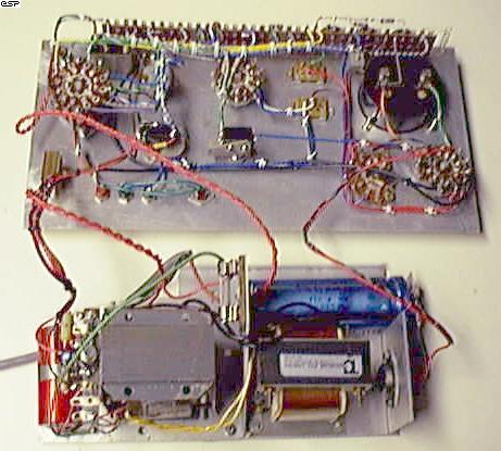 This
first picture shows the internals of the tester. The two power transformers
are clearly visible, along with the regulator (far right) and main filter
cap. The switching is all on the front panel, and consists mainly
of rotary switches. The sharp eyed may be able to see a relay hiding
at the top left of the panel. This was used because I could not get
hold of a suitable push button switch when I built the tester, so the extra
switching was obtained with the relay.
This
first picture shows the internals of the tester. The two power transformers
are clearly visible, along with the regulator (far right) and main filter
cap. The switching is all on the front panel, and consists mainly
of rotary switches. The sharp eyed may be able to see a relay hiding
at the top left of the panel. This was used because I could not get
hold of a suitable push button switch when I built the tester, so the extra
switching was obtained with the relay.
This unit is now over 25 years old, and is still going strong. I have had to fix it a couple of times, one of which was to replace the valve HV buffer with a transistor, and the regulator also failed once.
The switching has never caused a problem, but unlike the new design, this one uses trimpots for calibration. These need the occasional tweak to regain accuracy, but as seen in the circuits, this has been completely avoided with the new design (and a good thing too).
The tag strip I used to mount all the resistors on is visible at the top of the photo, but this requires far too much wiring. The new design requires very little - just a few interconnects here and there between the switches.
 The
second photo shows the front of the unit, which was hand lettered using
Letraset "rub-on" lettering, and sprayed with clear lacquer. It has
lasted rather well all things considered.
The
second photo shows the front of the unit, which was hand lettered using
Letraset "rub-on" lettering, and sprayed with clear lacquer. It has
lasted rather well all things considered.
If building the new unit, I suggest that you use a transistor socket (if you can get one) for the small signal transistors, and use banana sockets for leads to connect to power devices. Don't use the simple sockets like I did - you will regret it because they are a pain if you want to use double ended clip leads. Use combination binding post / banana sockets. These will allow you much greater flexibility when using the tester, and will also let you test transistors while still mounted on the heatsink (they must not remain connected to the rest of the circuit, though - this is NOT an in-circuit tester).
Happy transistor testing.
| Copyright Notice. This article, including but not limited to all text and diagrams, is the intellectual property of Rod Elliott, and is Copyright (c) 1999. Reproduction or re-publication by any means whatsoever, whether electronic, mechanical or electro- mechanical, is strictly prohibited under International Copyright laws. The author (Rod Elliott) grants the reader the right to use this information for personal use only, and further allows that one (1) copy may be made for reference while constructing the project. Commercial use is prohibited without express written authorisation from Rod Elliott. |