
Reprinted with permission from: Aubertin, M., Hassani, F. & H. Mitri, Rock Mechanics: Tools and Techniques: Proceedings of the 2nd North American Rock Mechanics Symposium, NARMS '96, Montreal, Quebec, 19-21 June 1996. 1996. 2102 pp. 2 vols., Hfl. 245/US$150.00. Please order from A. A. Balkema, Old Post Road, Brookfield, VT 05036 (telephone: 802-276-3162; telefax: 802-276-3837). Web site: http://www.jcn.nl/ima/balkema
Piezometers are employed to monitor construction activity below the ground water surface or where piezometric pressures may influence the stability of structures (e.g., locks, dams, levees, etc.). As such, piezometers are the most pervasive (in terms of numbers) of all geotechnical field instruments. With increasing emphasis on remediation of hazardous and toxic waste sites, use of ground water level monitoring devices is likely to increase. Traditional downhole submerged transducers for monitoring ground water elevations have not proven to be completely reliable and are time consuming and expensive to maintain. Transducers require relatively large riser pipes (usually greater than 25 mm I.D.) and must be calibrated and manually verified downhole.
This paper describes recent advancements in time domain reflectometry (TDR) instrumentation for monitoring ground water elevations and piezometric pressures. TDR takes advantage of the unique approach of pulsing a long coaxial cable and analyzing the reflected voltage signature caused by changes in impedance of the cable when submerged. While this technology has been employed for a variety of applications, recent development of a small, rugged time domain reflectometer that operates at low power has made TDR applicable for long-term field use. A reflectometer and supporting electronics are located at the surface where they are accessible and easy to maintain, and a non-electronic coaxial cable replaces the traditional downhole transducer. Installation is simple and does not require field calibration. Since only the cable is inserted in the hole, it can be employed with riser pipes as small as 12 mm inner diameter.
TDR technology for monitoring ground water is being developed and commercialized through the U.S. Army Corps of Engineers Construction Productivity Advancement Research (CPAR) program with a Cooperative Research and Development Agreement between the U.S. Army Corps of Engineers Waterways Experiment Station and HYPERLABS, Inc. The Infrastructure Technology Institute at Northwestern University is a primary participant in this cooperative research effort. Through the CPAR program a prototype time domain reflectometer has been designed and built and is currently under field evaluation. It is anticipated that this new device will significantly advance the practice of telemetric surveillance of ground water elevations.
Early civil engineering applications of time domain reflectometry (TDR) technology include measurements of ground deformation, such as displacement along rock joints (Dowding, Su and O'Connor, 1989). To deploy this monitoring system, a single solid dielectric, coaxial antenna cable is anchored to the bottom of a borehole and surrounded by an expansive cement grout that fills the hole. At the ground surface, this cable is connected to pulsing and monitoring electronics which record the reflected voltage signal along the entire length of cable. Originally, signals were collected on site with paper strip chart recorders. Today, the system can be remotely accessed and data electronically retrieved through existing telecommunications (Dowding and Huang, 1994).
More recently, use of air dielectric, coaxial cables and parallel wires for measuring water level and piezometric pressure has been described by Dowding, Huang and McComb (1996). Since these cables and wires can be inserted into existing riser pipes, this approach can be employed to retrofit piezometers for telemetric surveillance. This paper describes the basic principles of TDR that are employed to measure water level. To enhance field measurement capabilities, miniature pulsing and sampling cards have been developed to create a smaller and more rugged time domain reflectometer. Based on promising research, field experience in cable installation and telemetric monitoring, and the advantages offered by TDR technology, this reflectometer will optimize the measurement of water levels and piezometric pressures associated with construction activity or water retaining structures.
TDR is an electromagnetic technique originally developed to detect faults along power transmission lines. A time domain reflectometer, connected at one end of a cable, transmits an ultrashort rise time (200 ps), step voltage pulse along the cable and records the travel time and magnitude of all voltage reflections occurring at cable discontinuities. Changes in cable capacitance, impedance, inductance and resistance cause electromagnetic discontinuities that reflect voltage.
For water level monitoring purposes, discontinuities result from impedance changes produced by changes in the dielectric constant of the annulus between the inner and outer conductors of coaxial cables. Knowing the pulse propagation velocity of the cable, time-voltage measurements are converted to distance-voltage measurements, which are used to locate cable faults. Furthermore, voltage reflection profiles are unique for each type of discontinuity, allowing easy identification of impedance changes along inaccessible cables.
2.1 Water Level and Pressure Measurement
Various techniques have been employed to measure piezometric water pressure beneath dams and other structures. Most of these systems are based upon equilibration of standpipe water pressures with those at the measurement point, which usually consists of a porous stone or metal cylinder attached to a plastic tube. While the standpipe equilibration system is robust, pressure transducers which operate inside the standpipe are not, and often need to be recalibrated, repaired, or replaced.
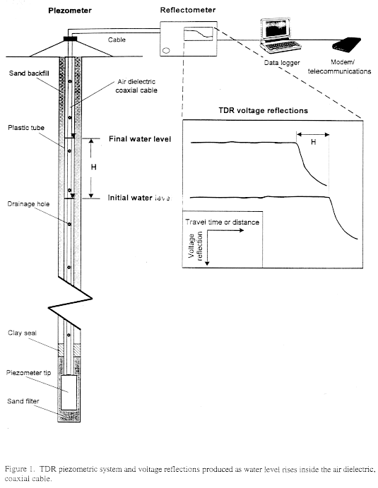
As illustrated in FIGURE 1, TDR water level measurements are made by launching a step voltage pulse down a known length of small diameter, hollow coaxial cable enclosed in a standpipe. The outer conductor of a hollow coaxial cable is separated from the inner conductor by a thin, spiral plastic, which allows air to fill the remaining space. This separation allows water to flow into the air space between the two conductors. A strong voltage drop at the air-water interface is produced by the difference in dielectric constant between air and water. Since reflection travel time is converted to distance along the cable, the voltage drop can be located on the cable. The initial point of the drop along the signal corresponds to the ground water elevation. When the system is in equilibrium, the measured height of the air-water interface above the porous tip times the unit weight of water is equal to the water pressure in the piezometer at the tip elevation. Equilibration of water level inside and outside the cable is accelerated by small drainage holes drilled into the outer conductor.
As the air-water interface moves up and down between the inner and outer conductors, location of the voltage drop shifts accordingly. As shown in the insert in FIGURE 1, the negative slope created at the interface moves to the left and toward the electronics by the distance H as the water level (and piezometric pressure) rises. Measurements can also be made as the water level falls. In this manner, a record of fluctuations in ground water elevations and/or piezometric pressures can be maintained with this system.
3.0 Advantages of TDR Measurement
3.1 Retrofit of Existing Porous Stone Piezometers
One of the most attractive advantages of TDR for digitized, electronic surveillance is its retrofit capabilities. Existing standpipe piezometers can be retrofitted with low cost, air dielectric coaxial cables to telemetrically detect the rise or fall of water levels in standpipes (Dowding et al., 1996). The stiff yet flexible air dielectric cables can be manually pushed through existing riser pipes that curve gently and do not meander. Small (9.5 mm O.D.) coaxial cables could be employed to retrofit systems with 12 mm inside diameter riser pipes.
Time domain reflectometers and other telemetry electronics would be installed in vandal-resistant enclosures at easily accessible but nonobtrusive locations on the ground surface or monitored structure. Since the electronics are above ground, they can be repaired or replaced easily. These "uphole" electronics also allow development of new strategies for avoiding transient-induced problems, such as lightning strikes or voltage fluctuations.
In the TDR system, the sensor is the inserted cable, which is passive and not susceptible to damage from transients. Electronic calibration is unnecessary since the sensing cable is self-calibrating through placement of voltage reflecting crimps, as described by Dowding et al. (1989). Measurements are typically referenced to these calibration markers, or crimps, of known dimensional separation on the cable, which eliminates the need for routine field verifications.
3.3 Multiplexing and Telemetric Surveillance
Multiplexing capabilities and remote accessibility of coaxial cables for measuring rock mass deformation are described by Huang and Dowding (1994). This multiplexing approach can also be employed with TDR measurements of water level and pressure. Presently, a single time domain reflectometer can be multiplexed to probe up to eight cables, but additional cables can be monitored by creating multiplexer levels.
Reflectometers can be controlled and data can be collected remotely via a modem or cellular telephone. Of course data can be collected directly from the electronics on site when necessary. By multiplexing several cables, response of multiple piezometers can be continuously monitored from a central unit. Thus a survey of an entire site or structure can be performed remotely with one reflectometer, saving time and reducing costs.
4.0 Miniaturized Field Reflectometer
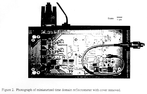
A miniaturized RS 232 interface time domain reflectometer is being developed and commercialized by HYPERLABS, Inc., the U.S. Army Corps of Engineers, and the Infrastructure Technology Institute (ITI) at Northwestern University for remotely monitoring ground water elevations and, ultimately, rock and soil shear deformation. The key to its development is the production of miniaturized pulsing and sampling cards (Agoston, 1996). This signal pulsing and recording instrument is designed to reduce the complexity and cost of current TDR monitoring electronics. The projected cost of the reflectometer is $3,000, representing a cost savings of 50 to 60%. Its employment with inexpensive, coaxial cables placed in existing riser pipes should reduce piezometric instrumentation costs by 20 to 40%.
This new device is small enough for packaging with other instruments, rugged, and low power consuming. A newly developed miniature pulsing card is linked to a separate microprocessing card (sampler), forming the core of the time domain reflectometer shown with the cover removed in FIGURE 2. The enclosed unit measures 191 mm by 89 mm by 50 mm, approximately 1/14th the size of present TDR units. The final product will be slightly larger when fully protected in a water resistant case. The reflectometer is expected to perform in harsh field environments, conditions that current electronics are not designed to sustain. Laboratory tests show that the pulsing card performs accurately in temperatures ranging from -40°C to +85°C. Power consumption is designed for a maximum of 1 watt.
Future developments of the field time domain reflectometer include modification of the communication protocol to the SDI-12 specifications for intelligent systems that have been promulgated by the U.S. Geological Survey. Thus the unit will be compatible with a wide range of telecommunication hardware and software, and as a result no new equipment or specialized personnel will be required for its adoption by industry.
5.0 Construction Productivity Advancement Research
The Construction Productivity Advancement Research (CPAR) program is designed to accelerate the development, demonstration and commercialization of products deemed important to the enhancement of the construction industry. The miniaturized field reflectometer, whose advantages for remotely measuring ground water levels and piezometric pressures have been described, will significantly advance the employment of TDR for ground water monitoring and other field applications. As such, its development qualifies for strong CPAR support.
Research, development, and demonstration activities are divided into the following five phases. Phase 1 covered the preliminary design and specifications of the reflectometer. Some of the important issues resolved at this stage include the conceptual design, materials research, form and function description, and prediction of performance based on past experience. Phase 2 included optimization of design, construction and laboratory demonstration of a prototype over a range of expected field conditions, such as extreme temperatures. Phases 1 and 2 were successfully completed in the fall of 1995.
Phase 3 involved the production of two commercial units for beta testing. Achievements during this stage include the final electronic and packaging design as well as the full specifications and operational procedures. This phase was concluded in the first half of 1996.
Field testing of the time domain reflectometer will be performed during Phase 4 of the CPAR program and is currently underway. Site selection and the demonstration and evaluation of two instruments are the principal tasks in this phase. The final phase, Phase 5, focuses on commercialization of the reflectometer, where concerns for pricing, compatibility and technology transfer are addressed.
6.0 Field Testing and Application of TDR-Based Piezometer
The U.S. Army Corps of Engineers Waterways Experiment Station (WES) is responsible for field testing of the prototype reflectometer and TDR-based piezometric system. The primary objective of the field test is an evaluation of the ability to accurately monitor ground water levels in a field environment over an extended period of time. Emphasis will be placed on retrofitting an existing Casagrande type piezometer and placement of a new piezometric system. Optimum deployment and instrument performance can be determined from these test installations.
The field site is located at WES in Vicksburg, Mississippi, where a coaxial cable will be inserted into an existing 100 mm diameter well cased in PVC pipe. The well screen is situated in the Glendon Limestone Formation. The bottom of the screen just penetrates the lower boundary of this stratum at a depth of 51 m. The Glendon Limestone overlies the Mint Springs Sand Formation, which is used locally as a shallow aquifer because of its high piezometric head. Piezometric levels in the test well rise to within 15 m of the ground surface.
The time domain reflectometer and supporting electronics (i.e., data logger, power supply, telecommunications) will be housed in a weatherproof case located at the well head. It is expected that piezometers will be maintained over a period of at least nine months so that sufficient data can be collected to evaluate the instrument performance under variable weather conditions. During the test period, several different cable systems will be evaluated, although an air dielectric coaxial cable is the most promising. In addition to monitoring long-term static water levels, at least two short-term tests will be performed to evaluate the ability to track transient water levels.
6.2 Water Pressure Measurement beneath a Dam
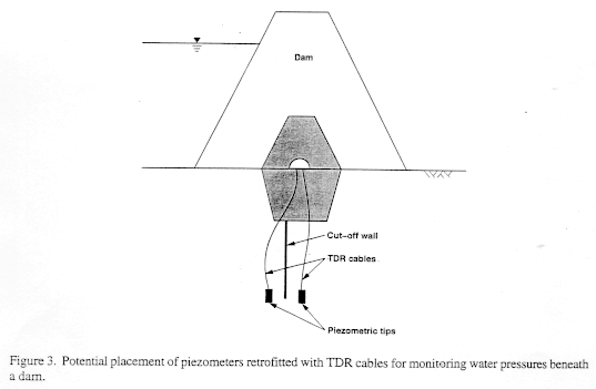
Phase 4 field testing will demonstrate that installation of a TDR-based piezometric system can be accomplished by retrofitting riser pipes or by simply placing new piezometers. One example application is shown in FIGURE 3, where lead cables running through an existing dam instrumentation channel can be attached to individual TDR-based piezometers. If piezometers are already in place but need to be upgraded, coaxial cables can be inserted into existing riser pipes and connected through long transmission lines to the electronics. If new piezometers are needed, the cable placement would be coordinated with their installation.
The instrumentation scheme depicted in FIGURE 3 suggests that piezometers can be placed at strategic, critical positions underneath the dam, such as on either side of a cut-off wall. A multitude of cable configurations can be installed on any dam or water retaining structure, but this depends on the type of dam or structure and specific monitoring objectives.
This paper describes advances in time domain reflectometry instrumentation and techniques for field deployment of a system to measure ground water levels and piezometric pressures. Installation can be accomplished by retrofitting existing piezometers with hollow, air dielectric coaxial cables or placing new TDR-based piezometers. Field performance of the cable monitoring electronics is expected to improve with the development and commercialization of a small, rugged time domain reflectometer, which is currently being field tested. Several advantages of TDR instrumentation include easy access to "uphole" electronics, pulsing of inexpensive cables, and most importantly, the ability to telemetrically survey piezometers and electronically collect and transfer data.
More detailed information on use of TDR techniques for geotechnical and infrastructure monitoring can be obtained from the Clearinghouse for Time Domain Reflectometry, located at the ITI world wide web site at the following address: http://iti.acns.nwu.edu/clear/tdr/index.html. In addition, ITI provides a listserv called TDR-L, which is essentially an electronic discussion forum on applications and issues in the TDR community. TDR-L can also be accessed from the clearinghouse.