| pH Meter Here's a circuit from the
datasheet for the National Semiconductor
LMC6001 ultra low input current amplifier. From the data
sheet...
Two
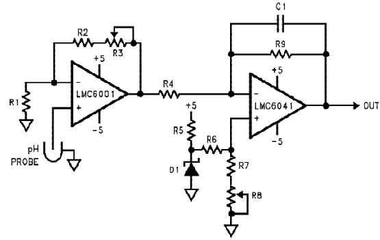
Opamp, Temperature Compensated PH Probe Amplifier
The signal from a pH probe has a typical resistance between 10 MΩ
and 1000 MΩ. Because of this high value, it is very important that
the amplifier input currents be as small as possible. The LMC6001
with less than 25 fA input current is an ideal choice for this
application. The theoretical output of the standard Ag/AgCI PH probe
is 59.16 mV/pH at 25șC with 0V out at a pH of 7.00. This output is
proportional to absolute temperature. To compensate for this, a
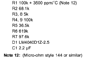
temperature compensating resistor, R1 , is placed in the
feedback loop. This cancels the temperature dependence
of the probe. This resistor must be mounted where it will be at the
same temperature as the liquid being measured.
The LMC6001 amplifies
the probe output providing a scaled voltage of ±100 mV/pH
from a pH of 7. The second opamp, a
micropower LMC6041 provides phase inversion and offset so
that the output is directly proportional to pH, over the full
range of the probe. The PH reading can now be directly displayed
on a low cost, low power digital panel meter. Total
current consumption will be about 1 mA for the whole system.
The micropower dual operational amplifier LMC6042 would optimize
power consumption but not offer these advantages:
- The LMC6001A guarantees a 25 fA limit on input current at
250C.
- The input ESD protection diodes in the LMC6042 are only rated
at 500V while the LMC6001 has much more robust protection that is
rated at 2000V.
The setup and calibration is simple with no interactions to cause
problems.
- Disconnect the pH probe and with R3 set to about mid-range and
the noninverting input of the LMC6001 grounded, adjust R8 until
the output is 700 mV.
- Apply -414.1 mV to the noninverting input of the LMC6001 .
Adjust R3 for and output of 1400 mV.
This completes the calibration. As real pH probes may not perform
exactly to theory, minor gain and offset adjustments should be made
by trimming while measuring a precision buffer solution.


Disclaimer
How to save and view
schematics
|

