|
Circuit Archives
Measurement & Control Circuits
/ Test
|
|
Four Channel Oscilloscope Adapter
Reprinted with permission
from Rudolf Graf.
For this and over 1000 other electronic circuits, review and order Rudolf
Graf's Encyclopedia of Electronic Circuits on CD-ROM Vol-1
McGraw-Hill ISBN0078528119

For a full size schematic of this circuit, view the PDF file version here. (You must have a copy of Adobe
Acrobat Reader to view this file.)

FD46-4
|
Description:
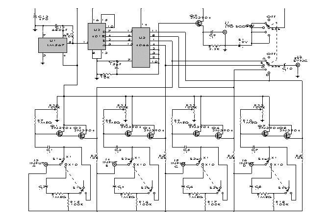
This simple adapter
uses an oscillator (567) to drive a counter (U2) and switch (U3) that selects the output
of one of the four scope preamps (Q1/Q2 through Q7/Q8) and feeds it to buffer Q9 and
output jack J1. J2 provides synch to the scope. R20 through R23 are posting controls for
channels A through D (J3 through J6). S1A-B through S4A-B are switched attenuators, one
for each channel. Switching rate is about 125 kHz. This circuit is useful for adding
four-trace operation to inexpensive oscilloscopes. Signal levels of 0 to 20 V can be
handled. (Reprinted with permission from Popular Electronics, 7/91, p. 59-61. Copyright
Gernsback Publications, Inc., 1991.) From figure FD46-4 of Encyclopedia of Electronic
Circuits on CD-ROM Vol. 1.
|
|

