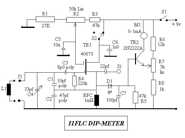
This circuit was developed by Luigi Falcone, I1FLC. He uses seven plug in coils covering 3.0 to 30Mhz in a Colpitts oscillator circuit. The coaxial socket J2 permits connection to a frequency meter when required. The coils are wound on Teflon formers with two "female" sockets which plug-in to two "male" sockets on the instrument. TR2 forms a DC amplifier permitting the use of a 1mA FSD meter with sensitivity controlled by R7. With TR1 switched off (via S2) the instument forms a field strength meter/RF sniffer.

| Range | Length | Diameter | Turns | L |
| (Mhz) | (mm) | (mm) | (uH) | |
| 3.0 - 4.5 | 30 | 21 | 75 | 59.6 |
| 4.0 - 5.8 | 25 | 21 | 63 | 47.8 |
| 5.0 - 7.5 | 19 | 17 | 47.5 | 23.5 |
| 7.5 - 11 | 10 | 17 | 25 | 10.25 |
| 10.5 - 16.0 | 11 | 11 | 27.5 | 5.55 |
| 15.0 - 22. 0 | 6 | 11 | 15 | 2.5 |
| 20.0 - 31.0 | 6 | 9 | 15 | 1.8 |
It is important that the oscillator components are mounted rigidly and not subject to "hand capacitance effects" in use.
If a somewhat larger value variable capacitor was used with a slow motion drive the number of coils to tune 3 to 30 Mhz could be reduced.