CONTINUITY TESTER
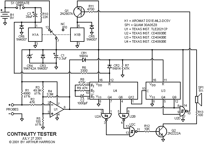
Among the essentials for circuit design and prototyping is the continuity tester, a simple device which provides an audible indication when a sufficiently low resistance is applied between its input probes. This version has a feature which automatically turns off the tester after about two minutes, thereby saving the 9 volt battery from inadvertent discharge. The tester produces a high-pitch tone when less than 10 ohms is placed between the input probes. The 10 ohm threshold is a convenient value that indicates hard-wired paths, but excludes indications for circuit paths through most components. In addition, the amount of current presented to the circuit by this tester is limited to less than 2 milliamperes at 9 volts, a level safe for most devices including small semiconductors. As an added convenience, automatic shut-off is immediately preceded by a low tone indication. The shut-off is inhibited by a continuity indication, which restarts the two-minute operating period.
Circuit operation is as follows: Momentarily pressing the "Operate" switch, S1, applies current through capacitor C3 to the set coil of a bistable mechanical latching relay, K1A. Once C3 charges, relay coil current is limited by resistor R10. This prevents excessive battery drain through the relay coil in the event that S1 is held closed. R10 serves to discharge C3 so that subsequent energization of the K1A coil is possible. When K1A energizes, the relay's contacts connect battery positive to the rest of the circuit. The momentary positive transition at C3's cathode is also applied, through resistor R6, to the reset input of oscillator/counter IC U4, and also through R6 and diode CR2 to the reset input of counter IC U3.
Operational amplifier U1 is used as a comparator with its positive input reference set by resistors R3 and R5. With the input probes open, the voltage at U1's negative input is equal to the supply voltage, provided through resistors R1 and R2. Under this condition, the output of the comparator is low. When a sufficiently low resistance is placed between the probe inputs, the voltage at U1's negative input becomes lower than its positive input, causing U1's output to be high. The threshold value for comparator transition is about 10 ohms of resistance. Resistor R2 provides current limiting for U1 in the event that an energized circuit is probed. Resistor R4 provides a small amount of positive feedback (hysteresis) for U1 to ensure clean transitions through the switching threshold.
IC U4's internal oscillator frequency is set at about 8,000 hertz with resistors R8 and R9 and capacitor C2. An audible frequency, about 8000/2^4, or 500 hertz, is present at U4's Q4 output. When the output of comparator U1 is high, the 500 hertz signal is gated through NAND gate U2A, appearing at its output. Initially, the pin 12 input of NAND gate U2C is high, allowing the 500 hertz signal to appear at its output. This signal is applied to the base of amplifier transistor Q2 via R12, producing a tone in the speaker, SP1. Resistor R13 limits the speaker volume to a reasonable level.
A 8000/2^6, or a 125 hertz audible frequency, is present at U4's Q6 output. This signal is provided to the pin-5 input of NAND gate U2B. U2B's other input (pin 6) is initially low. U4's Q12 output provides a 1.95 hertz clock to counter IC U3, which eventually accumulates enough counts to provide a high level at its Q9 output, switching U2B's pin 6 input to a high state, providing the 125 hertz signal at U2C's pin 12 input. With U2C's pin 13 in a high state, the 125 hertz signal is present at U2C's output, which in turn produces a low-pitched tone in the speaker. The low tone is maintained until U3's Q4 output transitions to a high state. This duration is approximately four seconds.
The high level at U3's Q9 output is NANDed with the high level at its Q4 output, providing a low level at U2D's output. This biases transistor Q1 into conduction via R11, energizing relay coil K1B, which in turn resets the relay contacts to the open position, disconnecting power from the circuit. No further battery current is consumed until the "Operate" switch is pressed again. If a high level at comparator U1's output occurs either before or during a low-tone interval, counter U3 will reset via CR1, resetting the approximate 2-minute interval preceding automatic shut-off.
Capacitor C1 provides power supply decoupling. Rectifiers CR3 and CR4 provide circuit protection from probe-applied voltages, and CR5 and CR6 provide transient clamping resulting from relay coil back EMF. Resistor R7 serves as a pull-down for the discrete OR gate formed by diodes CR1 and CR2. Although continuity measurements are performed with no regard for polarity, the probes are conveniently designated "+" and "-" for checking the polarity of devices such as LEDs.

June 30, 2001
Source documents dated October 16, 1992
Text and images ©2001 by Arthur Harrison
Back to the Circuit Library Index
Back to the Opening Page of Art's Theremin Page