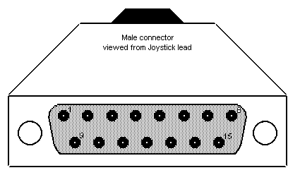
When wiring your connections to the Joystick port connector, it's easy to become confused with the pin numbers. Looking at the pictorial below, it should become clear where each pin is located.
If you look at the port on the rear of you PC, you'll notice there is always a 'female'-type connector. Counting from the top row, the pins start at number '8' through to '1'. The bottom rows start at pin '15' and end at pin '9'.
Just remember that the 'male'-type connector has the pin designations inverted.

| Pin | Designation |
|---|---|
| 1 | Joystick 1 +5v |
| 2 | Button 1 |
| 3 | Joystick 1 'X' axis |
| 4 | Joystick 1 Gnd |
| 5 | Joystick 2 Gnd |
| 6 | Joystick 1 'Y' axis |
| 7 | Button 2 |
| 8 | +5v |
| 9 | Joystick 2 +5v |
| 10 | Button 3 |
| 11 | Joystick 2 'X' axis |
| 12 | Midi In |
| 13 | Joystick 2 'Y' axis |
| 14 | Button 4 |
| 15 | Midi Out |
Best Regards... Pete
http://www.keirle.fsnet.co.uk