Horizontal bar

Some blinkers with neon glow lamps

Horizontal bar

The simplest blinker

Another simple application of these lamps is a simple blinker that uses the special U/I characteristic of these components.
The main voltage is rectified by the diode, a current flows through the resistor and slowly charges the capacitor. As long as the voltage remains below the trigger voltage (about 80 V) no current can flow through the lamp. When the voltage reach that value the gas in the lamp ionize and the capacitor discharges itself through the lamp generating a short flash, then the cycle starts again.

Diagram of the blinker

Now the lamp is fed with an unidirectional current and only the negative electrode glows.

Picture of the blinker

Remark: Depending on the type of the lamp some variations to the values of the components can be required.

Horizontal bar

The fuse monitor

Another application of the blinker above is the Fuse monitor: a neon glow lamp indicates by remaining lit that the fuse is in order, by blinking that the fuse has blown and by remaining off that there is no power.

Diagram of the fuse monitor

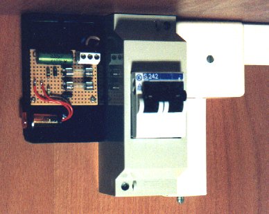
The diagram is very similar to the blinker: when the fuse is in order the two resistors (with the series diodes) are in parallel and the capacitor is charged very quickly since one of the resistor is only 150 KOhm (much smaller than the other one) and the lamp blinks very fast and gives the impression of being permanently lit. When the fuse blows the capacitor is charged only by the other resistor (of 2.2 MOhm) and the lamp now blinks slowly to indicate that the fuse has blown. If the main voltage drops the lamp remains off (obvious!).

Picture of the fuse monitor (internal view) Picture of the fuse monitor (external view)

I suggest to insert, in series with the two resistors, two fast fuses to ensure that the circuit remains safe even if a component of the monitor breaks.

Horizontal bar

A twin blinker

It's possible to make a twin blinker with two neon glow lamps that uses their non-linear U/I characteristic.
A DC voltage is now required and it's supplied by the diode and the high voltage electrolytic capacitor. This capacitor is quite difficult to find, but can be recovered from an old compact fluorescent lamp.
The resistor and the trimmer controls the frequency of the blinks and if an adjustment is not required both can be replaced with a single 1 MOhm 0.25 W resistor.
When one lamp lit the 150 nF capacitor is charged and the voltage on the other lamp rises. When the trigger voltage is reached the second lamp light and the first one is turned off by the negative peak generated by this capacitor.

Diagram of the twin blinker

This is quite a critical circuit and requires two identical glow lamps. Not every lamp will work fine and some adjustments could be required. Not every lamp will work for this circuit.

Picture of the twin blinker

Remark: This circuit will start working only a few seconds after it has been switched on, and, once switched off it will continue blinking for some seconds. The charge in the high voltage capacitor can be lethal even when the blinker is switched of: always discharge this capacitor before touching any part of the circuit!!!

Horizontal bar

Megaohmmeter

It's an odd application of a glow lamp blinker but allows measuring (with a poor precision) very high resistive values (up to 1000 MOhm). The resistor to measure is used to charge the capacitor of a blinker, and by counting the number of blinks each 10 seconds the value of the resistor can be determined.

Diagram of the megaohmmmeter

This "instrument" has three ranges: 10, 100 and 1000 MOhm and the indications in the table below are only indicatives, since the exact values depends on the tolerances of the components and on the characteristics of the glow lamp. In that table all values are valid for the case of 10 blinks in 10 seconds:

 Range  Unknown resistor 
 C = 4.7 nF  Rx = 1000 MOhm 
 C = 47 nF   Rx = 100 MOhm 
 C = 470 nF  Rx = 10 MOhm 

This circuit is directly connected to the main voltage and should not be touched, even the leads and the unknown resistor!!!

Horizontal bar

Back Back to the index. Home Back to the home page.
Previous Previous page. Next Next page.

Horizontal bar

Italiano Questa pagina è anche disponibile in italiano.

Horizontal bar