
Several people have asked me about determining the number of turns of wire for a particular frequency when building QRP radio projects. I have many times given the ROUGH "starting" point:-
Capacitance (pf) = Wavelength in meters
Coil turns aprox = Wavelength in meters<
Naturally the size of the coil former you use will affect the turns needed for a particular frequency, so this "starting" point is very rough and is only intended to get you in the right vicinity. A GDO is one of the most tools I posess, and I will describe one of these in another posting in the near future. To answer the first question for those who are interested in calculating coil turns, read on.
There are several formulas for calculating the number of turns required in any given application, but the results seem to differ quite a lot from one formula to another. I use two adaptions to Wheelers formula, one adaption for single layer coils and another for multi-layer (pile wound) coils.
The formulas assume that there is NO ferrite, or brass core to the coil. A ferrite core will reduce the number of turns by 10% to 25%, depending upon the size of the ferrite lump, and how far it is screwed into the former. A long ferrite rod can reduce the number of turns by as much as 50% to 60%. A brass tuning slug will INCREASE the turns required by typically 5% - 10%
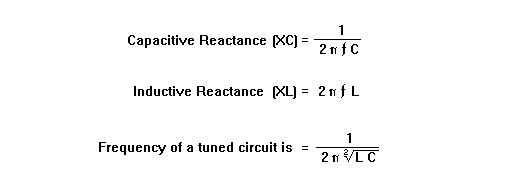
Just in case you have forgotten, you can calculate the value of required inductance, capacitance and impedance with these formulas, but I will not insult you intelegence explaining them.

At resonance Xc = Xl
Tap inductors; Impedance ratio = turns ratio squared

SINGLE LAYER COILS

where
L = inductance in micro-henries
l = length of the winding in inches
N = the number of turns
r = outside radius of the coil in inches
EXAMPLE.
I want a coil to have 20uH inductance in an HF PA valve anode for 30 MHz. I shall use a toilet roll tube for a former (2 inches in diameter). I will space the coil out so that the winding length is one inch.

Even 4mm Dia. Cu wire will allow 20 turns per inch, take your pick. If it burns when you apply power then use a thicker wire.

MULTI-LAYER COILS

where
L = inductance in micro-henries
a = winding thickness + former diameter in inches
b = length of winding in inches
c = winding thickness in inches
N = number of turns
EXAMPLE
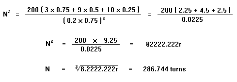
I want a coil for a 1MHz medium wave QRP pirate-radio transmitter amplifier stage tuned circuit. The inductance I need is 200uH. I will use a plastic bottle-top former, 0.5" Dia. I can allow a total of 1.0" for the coil diameter, and, it must be 0.5" long. (L = 200, a = 0.75", b = 1", c = 0.25")

This winding is .25" thick by .5" long. Total cross-sectional area of the coil is 0.125". I therefore need a wire thickness that will fit into this area = 2293.953 turns per square inch or thinner. 29 SWG (0.35mm Dia.) is the max thickness of wire I can use, according to the following table.

0.05 mm wire will handle 3 mA
0.10 mm wire will handle 12 mA
0.50 mm wire will handle 300 mA
1.00 mm wire will handle 1.25 amperes
4.00 mm wire will handle 20.10 amperes

Further reading:
1. "Radio and Telecommunication Engineers Design Manual" by R. E. Blakley. (Pitman). [Quite detailed]
2. "Coil Design and Construction Manual" by B. B. Babani. (Bernard Babani Publishing).[Simple presentation]
3. "The ARRL Handbook For Radio Amateurs" by the ARRL. (ARRL). [Information a little limited].

Have fun, de HARRY, Lunda, Sweden.
