COINSHOOTER Metal Detector
The Coinshooter employees a sophisticated, VLF induction-balance detection
system that responds only to the proximity of nonferrous metallic objects,
it ignores items containing iron. Moreover, the project can be adjusted
to compensate for the soils mineral
content, thus minimizing false indications. The Coinshooter can detect
a dime in an air test at four inches or a half-dollar at eight inches.
Depth of detection in the field will depend on ground conditions, but detection
depth will always be less than air test. Unlike detectors that employ
conventional beat-frequency oscillator circuits, the Coinshooter does not
require the user to monitor the pitch of a continuous tone. Rather, it
alerts the user to the proximity of nonferrous metal by generating one
or more beeps. Also, it is lightweight (about 2 lb.) and well balanced.
Total construction cost is approximately
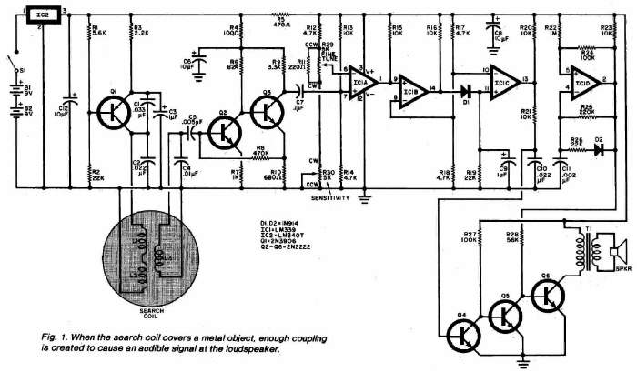
$35, and less if salvaged parts are used. About the Circuit. The Coinshooter
appears schematically in Figure 1. Coplanar search coils are formed by
placing a receiving coil (L3) over a folded-loop transmitting coil (L1
and L2) so that there is little if any coupling between them unless there
is metal present in the search field. A Colpitts oscillator comprising
Q1 and its associated passive components generates a 6.2-kHz signal that
drives the transmitting coil. Transistors Q2 and Q3 amplify the low-level
signal induced across receiving coil L3 when no metal objects are present
in the search field so that a 1-volt pp
signal appears at the collector of Q3. Capacitor C7 couples this signal
to the non-inverting input of voltage comparator IC1A. The input circuit
of the comparator rectifies the ac signal, resulting in the generation
of a slightly negative voltage that subtracts from the
positive bias voltage supplied by divider R13-R14. Potentiometers R29 and
R30 determine the magnitude of the reference voltage applied to the inverting
input of ICIA and hence the detector circuits sensitivity. They are adjusted
so that the voltages at the two inputs are practically equal. When the
voltage at the non-inverting input of the comparator becomes more positive
than that at the inverting input, the output terminal (pin 1) switches
to the positive supply voltage. This positive pulse toggles comparators
IC1B and IC1C, which are connected in.cascade and whose inverting inputs
are biased to one-half the positive
supply voltage. The charging of C9 via D1 and the discharging of C9 through
R19 stretches the pulse. Transistor Q4 is triggered into conduction by
the elongated pulse that appears at the output of IC1C, cutting off Q5.
When Q5 is cut off, Q6 amplifies the tone produced by the audio oscillator
comprising IC1D and its associated passive components. The current flowing
through the primary of audio-output transformer T1 and transistor Q6 increases
the voltage drop across R5, and this upsets the bias applied to the inverting
input of IC1A. As a result, the outputs of IC1A, IC1B, and IC1C go low,
transistor Q4 cuts off, and transistor Q5 saturates, shunting the base
drive of Q6 to ground and cutting that transistor off. This silences the
loudspeaker and allows C8 to charge again to the full positive supply voltage.
The higher voltage across the capacitor allows IC1A to change state again
if the nonferrous metal object is still within the search field. Iron objects
or mineralized ground within the search field will produce an increase
in the amplitude of the signal at the collector of Q3 and thus a less positive
bias at the non-inverting input of IC1A. In contrast, the presence of coins
or other. nonferrous metal objects within the search field will cause a
smaller signal to appear at the collector of Q3 and a more positive bias
at the non-inverting input of the first voltage comparator. This allows
the Coinshooter to locate coins and other items of interest while ignoring
nails, bottle caps, and other junk pieces of iron and steel. When
a small nonferrous item quickly enters and exits the search field, the
loudspeaker will generate a single beep. If the object enters and
remains in the search field, a series of beeps will be produced. Its rate
of repetition will vary with the settings of potentiometers R29 and R30,
the size of the object, and the distance between the object and the search
coil. The pitch of the beep is determined by the values of C11 and the
resistances in the feedback loop, as
well as by the supply voltage. Its frequency is nominally 1.3 kHz.
B1,B2 9v alkaline battery
C1 0.033 mF, 50v Mylar capacitor
C2, C10 0.022 mF, 50v Mylar capacitor
C3, C9 1 mF, 16v tantalum capacitor
C4 0.01 mF, 50v ceramic disc capacitor
C5 0.005 mF, 50v ceramic disc capacitor
C6, C8, C12 10 mF, 18v aluminum electrolytic capacitor
C7 0.1 mF, 50v Mylar capacitor
C11 0.002 mF, 50v ceramic disc capacitor
D1, D2 1N914 silicon switching diode
IC1 LM339 quad voltage comparator
IC2 LM340T-8 +8v regulator
L1, L2 Air-core inductor: 175 turns of No. 30
wire wound 9-1/2 inches in diameter (see
text)
L3 Air-core inductor: 550 turns of No. 38
enamelled wire on 3-1/2" diam.
Q1 2N3906 or similar pnp silicon switching
transistor
Q2 through Q6 2N2222 or similar npn silicon switching
transistor
The following, unless otherwise specified, are 1/4 watt, 5%-tolerance,
carbon composition fixed resistors.
R1 5.6 kW
R2, R19, R26 22 kW
R3 2.2 kW
R4 100W
R5 470W
R6 82 kW
R7 1 kW
R8 470 kW
R9 3.3 kW
R10 680W
R11 220W
R12, R14, R17, R18 4.7 kW
R13, R15, R16, R20, R21, R23 10 kW
R22 1 MW
R24, R27 100 kW
R25 220 kW
R28 56 kW
R29 5 kW, linear-taper potentiometer
R30 5 kW, linear-taper potentiometer with
shaft-actuated SPST switch
S1 SPST switch (part of R30)
SPKR 2-1/4 inch, 8W dynamic speaker
T1 1kW:8W miniature audio output transformer
Misc. - Suitable enclosure, perforated or printed-circuit board, single-conductor
shielded cable, hookup wire, No. 30 and No. 38 enamelled copper magnet
wire, battery clips, battery holders, circuitboard standoffs, grommets
or other suitable strain reliefs for shielded cable, PVC electrical tape
or silicone cement or other suitable insulating material, 12 -inch-by-
12-inch sheet of 1/4-inch plywood, monofilament fishing line, 3/4-inch
masking tape, epoxy, hot-melt, and PVC glues, 4 feet of 1/2-inch O.D.,
schedule 125 PVC pipe, 2 feet of 1/2-inch, schedule 40 PVC pipe, 90°
elbow PVC pipe joint, 135° elbow PVC pipe joint, tee PVC pipe joint,
PVC pipe cap, bicycle steering-bar handgrip, lead buckshot, resin sealant,
white paint, solder, hardware, aluminum foil etc.
Power for the Coinshooter circuit is supplied by two series-connected
nine-volt batteries. An IC voltage regulator provides a constant supply
potential to the rest of the circuit until the batteries are nearly exhausted.
Quiescent current demand is approximately 10 mA, so battery replacement
should be infrequent if alkaline cells are used. If desired, the Coinshooter
can be powered by a single nine-volt battery and the regulator IC omitted.
However, the circuit is sensitive to changes in supply voltage, and this
alternative is not recommended. But, if this approach is taken, an alkaline
battery must be used. Construction. Procure a circular form 9-1/2"
in diameter on which you can wind the transmitting coil. In assembling
the prototype, a hamper lid was used, but a mixing bowl or cardboard cylinder
would be suitable. Wind a layer of masking tape 3/4-inch wide around the
form so that the adhesive side is exposed. The tape will hold the wire
and make winding the coil much easier. Wind a total of 175 turns of No.
30 enamelled copper wire around then form, keeping the wire as close to
the center of the tape as possible. The last turn should exit the coil
at a point on the circumference 10 inches before the starting point is
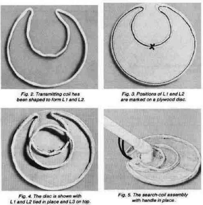
reached. Fold the tape around the coil and remove it from the form. Spiral-wrap
the coil tightly with masking tape. Then shape the coil assembly as shown
in Fig. 2 to form the
transmitting coil. (L1 is the large-diameter portion and L2 is the small-diameter
section.) The coils must be shielded so spiral wrap them (starting with
L1 opposite the lead wires) with 1" wide strips of aluminum foil.
Cover the coils completely except for a 1/4" gap between start and
finish of the foil layer. Strip a 6" piece of hookup wire and lay
it
on the foil so that 2" exits next to one of the lead wires. Then spiral
wrap the coils tightly with masking tape, covering the foil completely.
Slip the free ends of the shielded cables exiting the circuit-board
enclosure through the 1/4-inch holes that are bracketed by the smaller
holes and pass the cables through the pipe until they protrude from the
far end. Run a bead of hot-melt or epoxy glue on the pipe and attach the
bottom of the project enclosure to the pipe. Added mechanical support can
be introduced by driving self-tapping screws through the two small holes
in the bottom of the enclosure and into the matching holes that were drilled
into the pipe section.
Feed the free ends of the shielded cables through the two holes at the
other end of the pipe. Insert that end of the pipe into the elbow joint
attached to the plywood disc so that the circuit enclosure faces away from
the coil assembly. Then glue the pipe to the elbow joint using PVC cement,
maintaining the orientation of the enclosure with respect to the coil assembly.
(Note that PVC cement sets quickly.) Solder the conductors of the color-coded
cable to the transmitting coil and the conductors of the other cable to
the receiving coil. The polarities of these connections are unimportant.
Connect the coil shield leads to the outer cable conductors. Insulate the
solder joints using PVC electrical tape, silicone cement, or some other
suitable material. Then cement the cables to the plywood disc in the area
between L3 and the gap in L1 using hot-melt or epoxy glue. Cut 6- and 9-inch
lengths of 1/2-inch O.D., schedule 40 PVC pipe. Assemble a handle using
the lengths of pipe, a
90° elbow PVC pipe joint, a tee PVC pipe joint, a bicycle steering-bar
handgrip and PVC cement. The handgrip is glued to the 9-inch section of
pipe, and one of the two collinear openings of the tee should be glued
to the 39-inch pipe section to which the circuit-board enclosure and the
search coil assembly are attached. PVC cement is fast-setting, so work
quickly and orient the handle such that it is directly above the circuitboard
enclosure. The remaining end of the tee will be left open until the detector
is balanced. Apply power to the circuit and reconnect the oscilloscope
probe between the collector of Q3 and circuit ground.
Suspend the search coil in the air away from any metal and rotate the shaft
of R29 to its minimum-sensitivity setting. Monitor the scope trace
and, if necessary, slightly adjust the position of L3 so that a 1-volt
p-p signal appears at the collector of Q3. Pass a pair of pliers approximately
three inches under the search-coil assembly while monitoring the scope
trace. If the signal level decreases, shift L3 through the null point and
repeat the test. The signal must increase in amplitude when the pliers
are brought near the search-coil assembly, or the detector will ignore
coins and respond to the proximity of ferrous objects. Receiving coil L3
should be positioned as close to the null point as possible yet still provide
an increase in signal amplitude when iron or steel is brought near the
search-coil assembly. Next, pass a dime about three inches under
the search coil and note the slight increase in signal level as displayed
on the oscilloscope. Carefully fix the positions of the coils by bonding
them to the plywood disc with quick-setting epoxy cement. When the epoxy
has cured, remove the scope probe and button up the circuit-board enclosure.
Advance the setting of the SENSITIVITY control until the speaker begins
to beep. Then adjust the FINE TUNE control to silence the speaker. Pass
a pair of pliers three inches below the search coil and note that the speaker
remains silent. Then pass a dime three inches under the coil and note that
the speaker starts to beep. The most sensitive area of the search coil
is near its center.
The search-coil assembly can be coated with two thin applications of resin
to seal it, and then it can be painted white so that it matches the PVC
pipe. The coils must be bonded securely to the disc before the application
of sealant and paint. To minimize the possibility of displacing the coils,
use spray-on resin and paint. If the coils have shifted position before
the resin has cured, a compensating piece of iron or steel can be added
to the
search-coil assembly. Determine whether this has in fact happened by removing
the top of the circuit-board enclosure and reconnecting the oscilloscope
probe between the collector of Q3 and circuit ground. Pass a ferrous object
three inches below the search coil and monitor the scope trace. If the
proximity or iron or steel causes a decrease in signal level, position
a small steel washer on or near receiving coil L3 to correct for the misalignment.
Locate the required position by repeating the test for iron sensitivity
and shifting the location of the washer until the correct response is obtained.
Then fix the washer in place with epoxy cement. Final Assembly and
Use. Grasp the Coinshooter by its handgrip and check it for proper balance.
The search-coil assembly should be parallel with and approximately 2 inches
above the floor. Cut a 3-inch piece of 1/2-inch O.D. schedule 125 PVC pipe,
and glue one end of it to a PVC pipe cap. Fill the pipe section with lead
buckshot and tape its open end closed with PVC electrical tape. Then tape
the shot-laden pipe section to the open end of the tee PVC pipe joint and
recheck the balance of the project.
If it is unbalanced, untape the shot-laden pipe section, remove a little
shot, tape the section closed again and reattach it to the tee PVC pipe
joint. Recheck the balance of the Coinshooter. If necessary, repeat this
procedure until the Coinshooter is properly balanced and feels comfortable
to the hand. When the correct amount of shot has been
determined, remove the pipe section from the tee PVC pipe joint, seal the
shot in the pipe section with epoxy, and cement the section to the tee
after the epoxy has cured. This completes assembly. Take the finished
project outdoors and hold the search coil 4 to 6 inches above the ground.
Apply power to the project and adjust its controls so that the speaker
emits a slow series of beeps. Lower the search coil until it is approximately
2 inches above the ground. The beeping should stop. This occurs because
most soil is mineralized
and affects the Coinshooter much like ferrous objects do. The detector
is now at maximum sensitivity and will detect coins at depths of from 1
to 3 inches, depending on their sizes and positions. Ferrous objects will
not trigger the circuit unless they are very large or very close to the
search coil or both. The Coinshooter will detect aluminum cans, caps and
pull tabs, but it responds best to coins. Raise the search coil from time
to time to check for the slow beeps that indicate maximum detector sensitivity.
Although the circuit is very stable, the FINE TUNE control might have to
be adjusted occasionally to compensate for changes in
ground mineralization, temperature, and, if an unregulated power supply
is used, battery voltage. Always hold the Coinshooter so that the
search-coil assembly is 1 to 2 inches above and parallel to the ground.
Try to keep the search coil at a constant height above the ground. Swing
the loop back and forth in front of you, making overlapping arcs. It is
best to search slowly, but a coin will usually be detected even if the
search coil passes over it
quickly. For best results, operate the circuit as close to its switching
threshold as possible.
When an object has been detected, move the search-coil assembly over it
from front to back and from side to side to pinpoint its location. Keep
in mind that the center of the assembly is its most sensitive point.