 |  |
| Fig 1. (MK 1) | F 2. (MK2) |
try but to our surprise we were unable to make any real improvement on the first circuit
using the general principles. We could have reduced the package count by using
an LM389 (which in~cludes three independent transistors plus an audio output
amplifier) but that would have cost more with no real change.
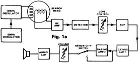
In the original design the transmitter was modulated and the peaks of
the detected signal were gated and enormously amplified (See How It Works and
Fig la). Although we refer to the signal being modulated, it was actually
switched on and off and this resulted in ringing in the tuned circuit.
After literally three weeks solid experimenting we decided to take
another approach. We decided to dispense with a modulated transmitter and work
with DC until the final stages. In the original design the audio frequency was
fixed, being dependent upon the modulator and metal was sensed by an increase
in audio level. However, our ears are highly insensitive to changes in level
but they are however, very sensitive to a change in audio frequency. Once we
had decided to tackle it from this side everything fell into place. For a long
while our voltage controlled oscillator was a unijunction transistor and
although we achieved excellent results we were not satisfied with the unit in
practice and eventually adopted the circuit shown in Fig.3.
FIp. la
(above) shows
the block diagram of the Mark 1. In thus the peaks of
the modulated signal wore gated and enormously amplified. Diagram below shows
the new arrangement. the RF signal, which is unmodulated, is converted to a DC
signal which delves a voltage controlled oscillator (VCO).
IRMk2
The Coil
We cannot emphasise
enough that the search head is the key to the whole operation: be prepared to
spend some time on this, our own workshop is full of discarded experiments.
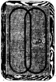
The housing
of the coils is not important. In the Mkl we adopted a circular head but this
is difficult for the non-woodworkers to tackle so we went for a rectangular
shape. The coils Li and L2 should be sandwitched between two pieces of
hardboard or plywood separated by thin battens
about 6mm
thick. The top should be built first and the battens fitted
for a
better appearance you can then file off the corners slightly.
To wind the
coils you’ll need to get hold of a cylinder about 140mm (5’Ain) in diameter.
Using 32 swg enamelled copper wire, trap one end onto the former with a piece
of tape and carefully wind 40 turns as close together as possible. Carefully
remove the coil and then wrap tape around it at intervals to keep it from
spreading.
Two
identical coils are required.
Lay one of
the coils into the dish formed from the top of search head and the battens as
you see in the photograph and spot glue it into place except on the part near
the middle. Lay the other coil next, again spot gluing it except near the
middle.
A hole
should be made in this piece of wood to feed through the connecting cable to
the main circuit. This cable must be a four-wire type with individual screening
the
screens are not used at the search coil end but don’t cut them too far back: we
still have a few experiments to try out on our prototype and access to this
screening may be used.
The
Control Box
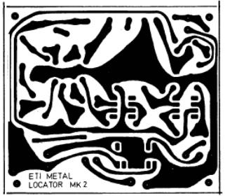
The circuit
should be built up next. Everything except for the controls, the speaker and
the meter are on a single POB. Building this up should present few problems.
Spacing is designed for
eighth watt
resistors and tantalums are used, again to save space though the control box
has plenty of room in
terminal pins to the points shown in the PCB overlay as this will make
connections far easier to make later on.
Assuming
you haven’t got the coil in exactly the right position by luck in the original
setting, you should get an audio tone of about 700Hz from the speaker and the
meter
connected) will be hard over.
If you
don’t get this, adjust RV 1 and it should appear: Back off RV1 until the
frequency falls and then increase it a bit so that the tone is slightly higher
than the minimum.
Now gently
and slowly bend the coils and adjust the overlap till the tone falls. Add a
fewmore blobs of glue but leave yourself with some adjustment. Readjust RV1
again and repeat. Continue to do this until you can no longer get any lower
adjustment on RV1.
Now check
that no metal
is
in the vicinity (don’t forget cuff-links, watches and
rings) and continue the manipulation.
If you use
a scope, monitor the level of the signal of the collector of Q2: when you are
near to a minimum
the level should fall considerably. If all works as
described, bringing
a piece of
metal near the coil should result in the frequency rising. If the frequency
falls instead of rising, continue adjusting. Near the minimum you can reach a
point where the metal firstly adds to the cancellation.
Don’t glue
down the final tiny, tiny adjustments until you are quite certain that all is
OK. The amount of final adjustment is extremely critical as you’ll find out.
General construction
The general
design can be seen from the photographs. We used a Verobox to house the main
circuit and cut a piece of broom-handle at an angle and fitted a bicycle
hand-grip to this. The stem is made up from Marley 22mm cold water plastic
tubing, available from many plumbers. The connection to the search-head was
accomplished by softening a short length of the stem plastic in hot water and
quickly clamping this in a vice. The connectors on the stem are
also Marley
fittings.
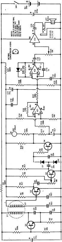
The heart of the circuit is the search coil, L1 and L2, These two coils,
which are essentially identical, are arranged in the same plane with a small
overlap in such a way that there is is practically no inductive coupling
between the two.
There is a minimum
pickup when the fields generated in L1 are cancelled in L2 when in free
air.
Any metal brought into the
magnetic field of L1 will distort the field, causing pickup in L2.
Q1 is a straightforward Colpitt’s oscillator working at a nominal 130
kHz. This type of circuit is very stable and the use of polystyrene capacitors
also help with stability.
The supply to
this stage is separately decoupled by R4 and C1.
The pickup coil L2 is tuned by means of C4 and C5 and amplified by Q2
which feeds th the level control RV1.
This controls the ‘free air’ state of the circuit and is set to the
point where the later stages are just operating.
The signal is further amplified by Q3 (here it is still an RF
signal) and is detected by D1 and D2.
When no metal is in the vicinity of the search coil and with RV1
correctly adjusted, a DC voltage of about 500 mV appears across C8.
R9 increase the effective input impedance of
Q4 as seen by the detector stage.
Q4 is just held off by the voltage available but as soon as metal
distorts the electromagnetic field, L2 produces a large RF signal, a higher
voltage across C8 and a consequent fall (from 8V) in the voltage at the
collector of Q4.
This voltage is also
monitored by the meter in parallel with the load resistor of Q4.
The fall in voltage is dependent upon the
proximity and/or size of metal near the search coil.
It is necessary to ensure that the DC voltage fed to the next stage is
clean and R12 and C9 act as a a filter to remove any residual AC even if this
is at low frequencies.
IC2 (the next but one stage) is a voltage controlled oscillator – but to
operate this so that metal is indicated by a rising note, rather than a falling
one, the voltage at the junction of C9 and R12 has to be inverted and this is
achieved by IC1: in ‘no metal’ conditions there is about 2 V at the output of
this op-amp which rises when metal is near.
This stage quickly saturates to give about 7 V at pin 6.
IC1 has unity gain.
IC2 is a voltage controlled oscillator in ‘no metal’ conditions it gives
about 70 Hz which rise to 500 Hz when metal is present.
Diode D3 gives a rapid recharge to C12 and
affects the mark/space ratio of the output which results in lower battery
consumption.
R20 and C12 can be altered
to give a different range of frequencies if desired.
The output is taken to the volume control and fed to the LM380 audio
power amplifier which in turn feeds the speaker.
The levels of signal around Q2,3,4 are all dependent upon transistor
gain, temperature and supply voltage but this doesn’t matter because the level
control RV1 is adjusted until Q4 just begins to conduct.
Current drain for the complete circuit is in the order of 50 mA.
| Resistors (all at 1/8W 5%) | |
| R1 150k | C13 1n polyester |
| R2 39k | C15 47u 16V electrolytic |
| R3,12 1k | C16 470u 16V electrolytic |
| R4,21 180R | |
| R5,7 1M | semiconductors |
| R6,8,10 4k7 | Q1,2,3,4 BC 184L or equivalent |
| R9,14,15 10k | IC1,2 741 8-pin DIL |
| R11,13,16,17 100k | IC3 LM380 |
| R18,19 220k | D1,D2 OA91 |
| R20 120k | D3 1N914 |
| RV1 1M linear (level) | |
| RV2 10k log (volume) | Miscelaneous |
| Capacitors | LS1 8 ohm minature loudspeaker |
| C1,11 47u 16V tantalum | JK1 stereo jack socket |
| C2 3n3 polystyrene, 5% | M1 100uA level meter |
| L1,L2 see text | |
| C3 10n polystyrene, 5% | PCB - see drawing |
| C4,C5 20n polystyrene | 4-core individually screened cable |
| C9,14 4u7 16V tantalum | Battery and Clip pp9 |
| C10,12 100n polyester | Bicycle hand grip |
| Verobox, 4 1/4 x 7 1/2 x2 1/4 |
Re printed from ETI TOP PROJECTS NO7 (1979)