| E-mail this page to a friend | Tell me when this page is updated |
| E-mail this page to a friend | Tell me when this page is updated |
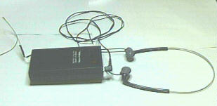
1. One pair of Realistic voice actuated fm tranceivers Model TRC-500 Cat#21-400 or a similar system (they may have replaced this unit with a newer version, it should still work).
2. One three conductor 1/8" phone jack Radio Shack Cat# 274-249.
3. About 18" of cable with stereo plug attached from an old walkman type headphone.
4. Whatever adapter you may need to plug the stereo plug into your detector.
5. About 3' of two conductor bell wire.
6. One disk capacitor, value 100PF (purchased at radio shack CAT#272-123)
Screwdriver, soldering iron, tool to cut cord mount from case (nippers). Wire cutters and strippers.
Next disassemble the earpiece of the headphones so you can identify what wires go to what part (there are wires there for antenna, speaker, and mike). This will help if your unit is not exactly the same as the one I used. Trace them from the headset to the circuit board and make a note of where they are attached to the board.
Once you are familiar with the layout of the wires and their connection points you are ready to begin the conversion. I suggest you do only one unit at a time so you have the other one to look at if you need to.
We will make the first unit the transmitter. Begin by stripping the cover off about 3" of the stereo wire with the plug atached. Twist the shield braid (this goes to the shield of the plug, the part closest to the molded plastic finger grip of the plug) to form a single wire and lightly solder it to hold it together. There are two other wires inside the braid, only one of these are used (I used the red one, it is connected to the tip of the plug). Unsolder the mike wire and mike ground from the circuit board. Place the shield braid into the ground hole in the circuit board and pull it through until there is no bare wire left exposed on the component side. Solder it to the foil side of the board and clip the excess off. Measure the red wire and cut it to length to reach the mike input on the board but do not attach it yet. Strip about 1/4" of insulation from the red wire and tightly wrap it arount one lead of the 100PF capacitor as close to the capacitor as possible and solder it together. Trim the excess lead off that side of the capacitor and tape it so it is not exposed. The other end of the capacitor goes into the mike input on the circuit board. (the capacitor isolates the voltages from the receiver and detector) Pull it tight to the board, solder in place and clip off the excess lead from the foil side of the board.
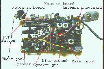
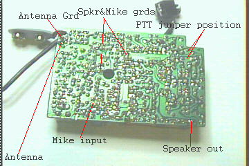
| Receiver illustration, the points for the transmitter are identified here also. | |
|---|---|
 |
 |
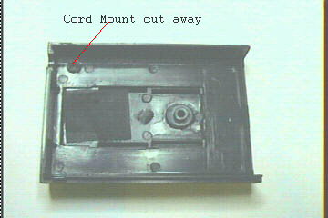
Locate the Push to Talk button (PTT), examine where the leads from it attach to the board. You will have to put a jumper between the two leads so the unit is on transmit all the time. I have identified the position in the illustration but the jumper wire is not shown. I used a push on- push off type switch on mine but a jumper is easier. Next unsolder the speaker wire and ground and remove the headset wire harness from the unit. You will have to spread the cord clip to be able to remove it, do this carefully because you will use the clip to hold the new input wires in place. Tie a knot in the new input wires close to the board and place the knot behind the cord clip, place the antenna wire in the clip also and recrimp the clip. You can now reassemble the unit. Once the unit is assembled separate the two conductor bell wire into single wires. Remove about 1" of insulation from the antenna wire and trim the braid close to the insulation, this will leave only the center conductor extending from the insulation. Strip about 1/4" from the center conductor and bell wire and solder them together, tape the joint and you are done with the transmitter. I wraped the antenna wire around the unit but you can wrap it around the detector if you wish. Experiment with what works best for you.
Now on to the receiver. Unsolder the mike input and ground, they are not needed. Unsolder the speaker output wire and it's ground. Strip about 3" of the outer cover from a 6" piece of shielded wire, twist the shield together and solder to hold it tight. Place the shield in the speaker ground hole on the board, pull it tight so no bare wire is exposed, solder and trim the wire. Route the center conductor to the speaker output of the board and cut it leaving a little excess to strip the lead. Insert the wire into the board at the speaker out position pull tight, solder, and trim.
Unsolder the antenna wires and replace them as you did in the transmitter and route them out through the battery compartment, you will need to make a small notch in both sides of the case to allow for this. Tie a knot in the wire so it will fit inside the case for strain relief. Add the bell wire to the antenna wire as you did in the transmitter. (I laced this wire around my utility belt wrapping it from the middle of my back around the right side to the front of the belt.) Reassemble the unit clip the receiver to the back of your belt and plug in the headset.