|
Darkness
Controlled Light switch
|
| Street
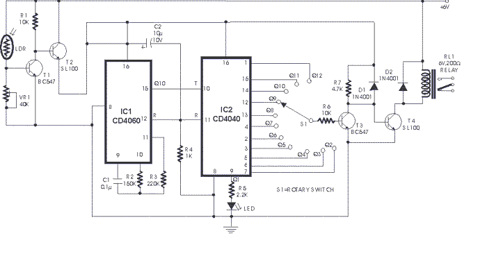
lights as well as lights at home and most public build-
ings or industrial units need to be switched on at night
and switched off at a specified time in the morning. Here
is an LDR based circuit which will perform these functions
automatically. The dark resistance of an LDR is of the
order of a few mega-ohms while its resistance in presence
of light drops to a few kilo-ohms. In darkness, transistor
T1 does not get sufficient forward bias current and is
cut-off. This causes forward biasing of transistor T2
and, as a result, the power supply becomes available to
the rest of the circuit. IC1 (CD4060) functions as a square
wave generator. The output waveform is initially low and
goes high at 50 percent of time period at the output pin.
The basic oscillator time period is given by the formula:
T (time period) =2.3xC1xR2 sec. This basic clock is divided
within this 14-stage binary counter. In this circuit the
output of the 10th stage at pin 15 is used. The output
pulse period of IC1 is multiplied further by IC2 (CD4040),
which is a 12-stage binary counter. Any one of the outputs
(Q2 to Q12) may be selected using rotary switch S1. Q1
output of IC2 has been used for LED blinking to show that
circuit is functioning. The final output, which is initially
at logic low, is fed to transistor T3 which is thus cut-off.
This results in forward biasing of transistor T4 which
causes relay RL1 to be energised. AC supply to the lighting
load is thus connected via the contacts of this relay.
The relay will remain energised till either the selected
output of IC2 goes high or the LDR resistance falls to
a low value due to light. The sensitivity of transistor
T1 may be adjusted with the help of preset VR1. |
|
|
Click on the Image for it larger version
|