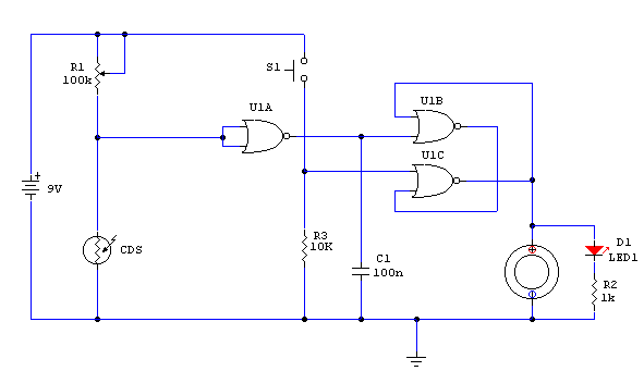
Light Detector Circuit

Kindly submitted by Mick Devine from the UK
Notes:
Variable resistor R1 adjusts the light threshold at which the circuit triggers. R1's value is chosen to
match the photocells resistance at darkness. The circuit uses a CMOS 4001 IC. Gate U1a acts as the trigger,
U1b and c form a latch. S1 resets the circuit. The output device may be a low power piezo buzzer.

