| PHY311/312 |
Nuclear and Particle Detectors |
Dr C N Booth |
Scintillation Counters
Scintillation counters exploit the atomic or molecular excitation
produced by a charged particle as it passes through matter. Full
details of these detectors are given in the handout, PostScript
and PDF versions of which are available.
This page
contains a very brief summary of the key features of scintillation counters,
with links to relevant sections of the
Particle
Detector BriefBook.

A scintillation
counter is composed of four main components: a sheet of scintillator,
a light guide, a photomultiplier and the electronics in the p.m. base required
to drive the photomultiplier and read out the signal.
-
There are two main types of scintillator, inorganic (such as sodium
iodide) and organic (such as a plastic like polystyrene).
The passage of a charged particle through the material excites electrons,
which can subsequently de-excite, emitting a photon. However, this
photon would normally be of exactly the correct energy to be reabsorbed
by the material. A small concentration of
a wavelength
shifter is therefore added. This allows rapid non-radiative
transitions of the excited electron, reducing its energy so that the photon
subsequently emitted is of longer wavelength and insufficiently energetic
to be reabsorbed. The scintillator sheet is highly polished, and
light is conducted along it by total internal reflection.
-
Light must then be transmitted from the scintillator to a sensor.
This is done by a light
guide. A typical shape is that of the "fish tail",
as illustrated above, which connects from the long thin edge of the scintillator
to the circular end of a photomultiplier. Other, more complicated
geometries are also used, for example to connect a number of scintillator
sheets to a common photomultiplier, e.g. in a calorimeter.
-
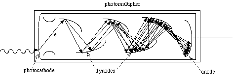
The photomultiplier
converts the optical signal to an electrical one, and provides a large
degree of amplification.
This consists of an evacuated glass envelope coated at one end with
a photocathode made of alkali metals, which is maintained at a large
negative potential. Photons liberate electrons from the cathode,
which are accelerated towards a (less negative)
dynode,
and here knock out a number of secondary electrons. This process
continues down the dynode chain, until eventually a large signal is collected
at the anode. Typical gains are of the order of 107.
If the signal drives a 50 ohm load, a pulse of a few mV per detected photon
is produced.
-
Connections to the photomultiplier are made through the photomultiplier
base, which contains a chain of resistors to provide the correct
voltages for the cathode and dynodes.
Applications
Scintillation counters typically have a poor spatial resolution (equal
to the size of the counter, which can be anywhere between a square cm and
a square metre) but, at least for small counters, a very good time
resolution. They are also continuously sensitive, and are therefore
often used as triggers
for other types of detectors, which must have a high voltage pulse applied
or a readout sequence initiated in order to observe a particle. A
pair of scintillation counters placed some distance apart can be used to
measure the time of flight of the particles. If other information
is known, such as the momentum of the particles (e.g. from their curvature
in a magnetic field), then the mass and hence identity of the particle
can be determined.
Layers of crossed scintillation counters are also used to form a hodoscope,
where the position of the particle can be determined from the coincidence
between signals from counters in the different layers.
Another application of scintillators is within calorimeters.
Because of their short radiation
length, inorganic scintillators make sensitive electromagnetic
calorimeters, and are often used to detect medium energy gamma rays.
Sheets of plastic scintillator between metal plates are used in sampling
calorimeters. Here, the number of particles at a particular depth
in a shower
can be determined from the size of the pulse observed in the scintillator.
Detectors with a good spatial resolution can be made by forming layers
of plastic optical
fibres made out of scintillator material coated with a lower refractive
index cladding.
These can typically have a diameter of 0.5 to 1 mm. The small size
of each independent scintillator means that many readout channels (typically
tens of thousands) are required, and it is not practical to equip each
one with its own photomultiplier. One solution to this is to gather
the fibres into a bundle and connect to an image intensifier.
This amplifies the light while maintaining an image, which can then be
viewed with a CCD camera, and the position on the image associated
with a particular fibre. One price paid for this solution, however,
is that the readout is now very slow (several ms), and the image intensifiers
often have to be gated to ensure only interesting interactions are recorded.
Back to PHY311/312 Page


