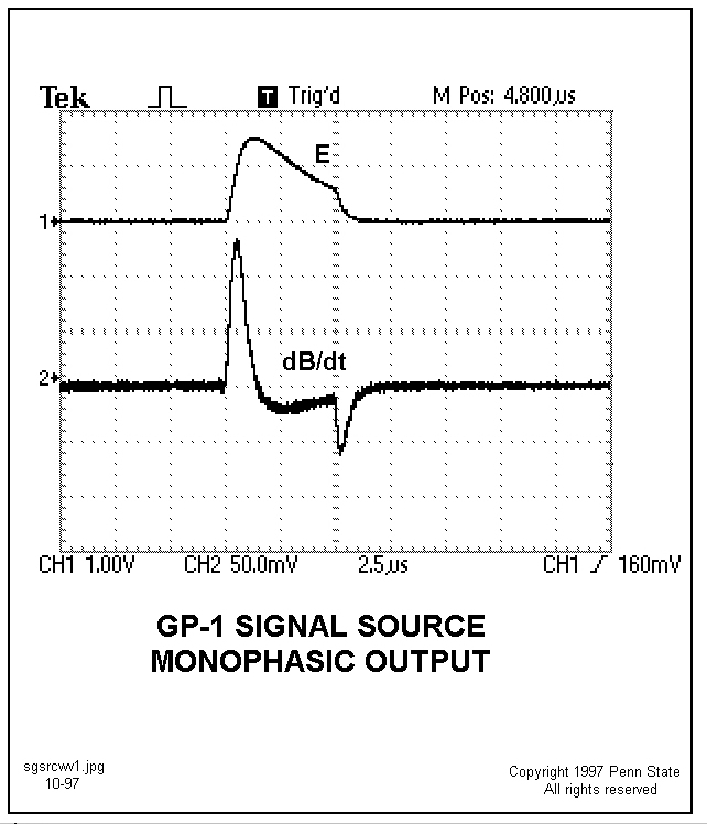
 Output waveshapes from the Signal
Source with switches set to Hi-, NR-, Mono-, and 100pf-positions
(upper figure) or to Hi-, NR-, Biph-, and 100pf-positions
(lower figure), as seen on a 2-channel oscilloscope. The waves in the upper figure approximate
a negative return stroke within 100 km, and the waves in the lower figure
approximate a negative intracloud stroke. Vertical sensitivity for each
'scope channel (CH1 and CH2) is as indicated. Sweep rate is 2.5 microseconds
per large division. E is the voltage field signal terminated by a
100pF capacitor. The signal dB/dt is obtained from a temporary 1-turn loop
of wire taped to the pipe square. The active terminal of the 'scope probe
is connected to the 1-turn loop end adjacent (hi end) to the front
panel and the probe ground terminal to the other (low end) end of
the loop. The waveshape obtained is the rate of change of the magnetic
field generated. When integrated in the Antenna Array magnetic field
circuits, the waveshape, B, will be identical to that
of the E-field, above. Both E and dB/dt waves are inverted when S2 is in the PR position to simulate a positive
return stroke in the upper figure and a positive intracloud stroke in the
lower figure. When S3 is switched to Lo, a stroke beyond 200
km is simulated.
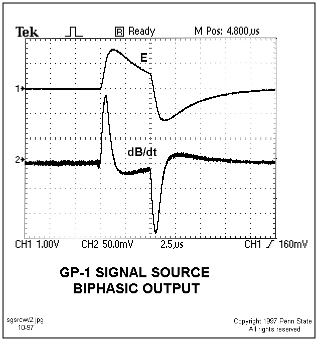
Output waveshapes from the Signal
Source with switches set to Hi-, NR-, Mono-, and 100pf-positions
(upper figure) or to Hi-, NR-, Biph-, and 100pf-positions
(lower figure), as seen on a 2-channel oscilloscope. The waves in the upper figure approximate
a negative return stroke within 100 km, and the waves in the lower figure
approximate a negative intracloud stroke. Vertical sensitivity for each
'scope channel (CH1 and CH2) is as indicated. Sweep rate is 2.5 microseconds
per large division. E is the voltage field signal terminated by a
100pF capacitor. The signal dB/dt is obtained from a temporary 1-turn loop
of wire taped to the pipe square. The active terminal of the 'scope probe
is connected to the 1-turn loop end adjacent (hi end) to the front
panel and the probe ground terminal to the other (low end) end of
the loop. The waveshape obtained is the rate of change of the magnetic
field generated. When integrated in the Antenna Array magnetic field
circuits, the waveshape, B, will be identical to that
of the E-field, above. Both E and dB/dt waves are inverted when S2 is in the PR position to simulate a positive
return stroke in the upper figure and a positive intracloud stroke in the
lower figure. When S3 is switched to Lo, a stroke beyond 200
km is simulated.