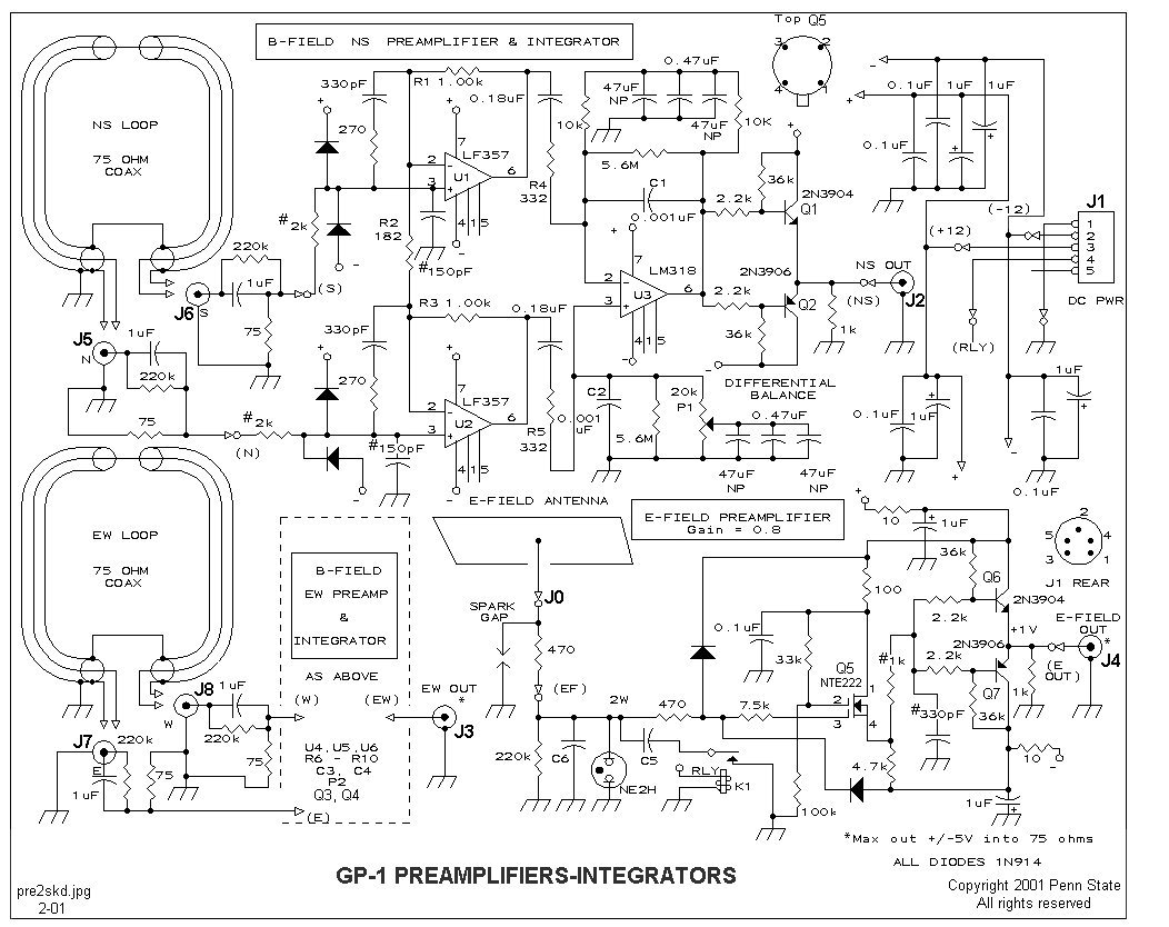
 The Preamplifiers-Integrators
circuit diagram. Note that the EW preamplifier-integrator is identical
to the NS preamplifier-integrator that is shown completely in the top center.
All resistors shown with three significant figures are 1%, 1/4-watt carbon
film. All other resistors are 5%, 1/4-watt carbon film. Polarized capacitors
are 35 V tantalum. C1 to C4 are 50 V polyester film capacitors (Panasonic
B-Series, Digi-Key), matched within 1%. Capacitors in picofarad units can
be either zero-temperature-coefficient ceramic (Panasonic Monolithic Type
COG) or dipped-silver mica; the remainder are polyester film. C5 determines
the E-field gain when the attenuator relay is closed, 200pF to 2700pF.
Similarly, C6 sets the normal gain, 100pF to 1600pF. See text. Trim pots,
P1 and P2, are 6-mm cermet (Panasonic Series 36C). Relay is a 12 V SPST
reed relay (Radio Shack 275-233). Components marked with # make up the
first pole of the 5-pole low-pass filters. See text under Low
Pass Filter Construction. Note Spring 2001: Q7 was originally specified as an RCA 40673 but is no longer available.
The NTE222 is a replacement item with identical characteristics.
The Preamplifiers-Integrators
circuit diagram. Note that the EW preamplifier-integrator is identical
to the NS preamplifier-integrator that is shown completely in the top center.
All resistors shown with three significant figures are 1%, 1/4-watt carbon
film. All other resistors are 5%, 1/4-watt carbon film. Polarized capacitors
are 35 V tantalum. C1 to C4 are 50 V polyester film capacitors (Panasonic
B-Series, Digi-Key), matched within 1%. Capacitors in picofarad units can
be either zero-temperature-coefficient ceramic (Panasonic Monolithic Type
COG) or dipped-silver mica; the remainder are polyester film. C5 determines
the E-field gain when the attenuator relay is closed, 200pF to 2700pF.
Similarly, C6 sets the normal gain, 100pF to 1600pF. See text. Trim pots,
P1 and P2, are 6-mm cermet (Panasonic Series 36C). Relay is a 12 V SPST
reed relay (Radio Shack 275-233). Components marked with # make up the
first pole of the 5-pole low-pass filters. See text under Low
Pass Filter Construction. Note Spring 2001: Q7 was originally specified as an RCA 40673 but is no longer available.
The NTE222 is a replacement item with identical characteristics.