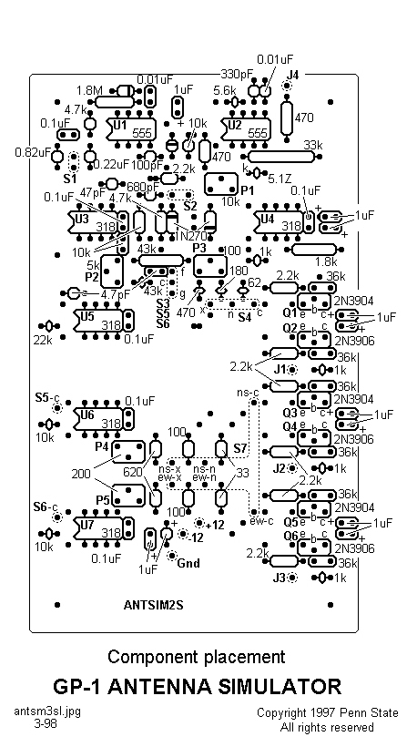
 Parts placement on the component
side of the circuit board. Flying leads connect the dashed-line-enclosed
pads to external components and should emerge from the component side of
the circuit board. For the switches, "c" indicates the common (rotor)
switch terminals, "x" indicates the max-position terminals, and
"n" indicates the min-position terminals. Note that S3-S5-S6
"f" connects to the switch S3 inv-position terminal, then on to
S5 S-position terminal, and then to S6 W-position terminal.
Similarly, S3-S5-S6 "g" connects to S3 norm-position terminal,
then on to S5 N-position terminal, and then to S6 E-position
terminal. Again, S3-S5-S6 "c" connects to S3 common, then to S5 common,
and then on to S5 common terminal. When the board is mounted in its
suggested cabinet, the left edge, as shown above, is the top and the right
edge is the bottom; see text.
Parts placement on the component
side of the circuit board. Flying leads connect the dashed-line-enclosed
pads to external components and should emerge from the component side of
the circuit board. For the switches, "c" indicates the common (rotor)
switch terminals, "x" indicates the max-position terminals, and
"n" indicates the min-position terminals. Note that S3-S5-S6
"f" connects to the switch S3 inv-position terminal, then on to
S5 S-position terminal, and then to S6 W-position terminal.
Similarly, S3-S5-S6 "g" connects to S3 norm-position terminal,
then on to S5 N-position terminal, and then to S6 E-position
terminal. Again, S3-S5-S6 "c" connects to S3 common, then to S5 common,
and then on to S5 common terminal. When the board is mounted in its
suggested cabinet, the left edge, as shown above, is the top and the right
edge is the bottom; see text.