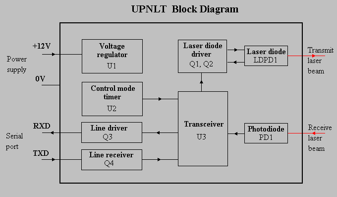

The voltage regulator uses a 78L05 IC to provide a stable 5 volt supply for all the other sections of the UPNLT.
The control mode timer uses a 555 timer IC to hold the transceiver IC data/control input low for about seven seconds following power up. While this input is held low, the transceiver interprets data it receives from the serial port as configuration commands.
The line driver inverts data received via the laser link and drives the serial port RXD line.
The line receiver inverts data received from the serial port TXD line and shifts the level to suit the transceiver IC.
The transceiver, Crystal Semiconductor's CS8130-CP, performs many
of the critical and complex functions required for an optical data link.
It is a multi-standard device, and for the UPNLT is configured to provide
IrDA SIR modulation and demodulation.
In the receive path the CS8130-CP provides a high-gain PIN diode amplifier
with compensation for ambient DC light, high and low pass filters, threshold
detection and demodulation. Bit timing is regenerated.
In the transmit path it provides modulation and an LED driver. Again, bit
timing is regenerated.
Regeneration of bit timing in the transceiver reduces the effects of optical noise. It also prevents the accumulation of minor phase shift errors, allowing longer cables between computer and UPNLT and simplifying chaining of UPNLTs.
IrDA SIR modulation has a number of advantages over other modulation schemes.
The laser diode driver limits the current flow through the laser diode to an absolute maximum value, and also regulates it on the basis of the signal from the monitor photodiode integrated into the laser diode package. R1 limits the average current through the laser diode, which reduces laser output if the duty cycle is greater than 20%, the maximum required for IrDA SIR.