New Schematic in Gif format(82kb)
New Schematic in PostScript format(250kb)
Important Construction Notes This is a MUST READ.
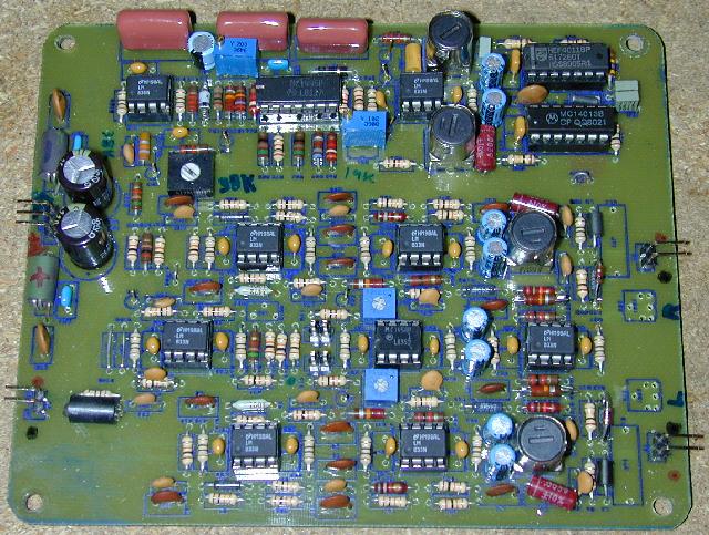
Top photo of home-made circuit board(95kb)
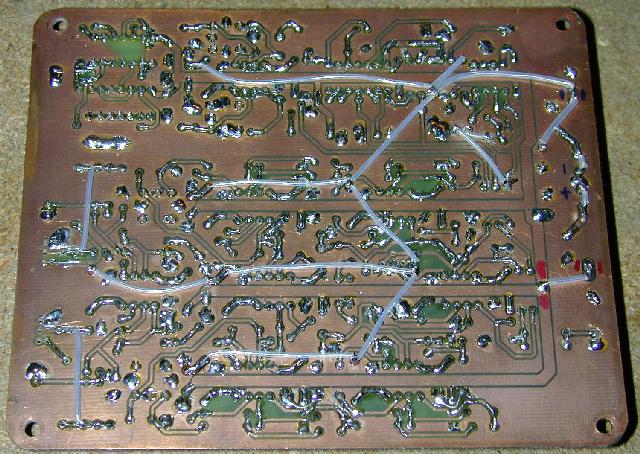
Bottom photo of home-made circuit board(90kb)
Wires are used in place of top PC layer.
Zip file bundle
containing the new schematic, docs, boards, pix(3.5mb) This can take 15
minutes or more to download with a modem.
Be sure to download the Construction Notes above.
Alternate Site(3.5mb) for the Bundle
Another Alternate Site(3.5mb) for the Bundle
"Lord Milson" sent me two CAD files for this circuit board in
Protel format, I have not tested
them out, but you may find them of use.
protel1.zip (380K)
protel2.zip (460K)
FRB 1W No Tune Xmitr Modifications
that are required to use this circuit (PostScript format)
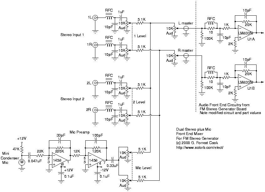
Dual stereo mixer
plus mic front end for the stereo modulator (Jpeg format)
Dual stereo mixer (PostScript format)
I have located a source of hard to find 38khz crystals, Digi-Key, 1-800-344-4539, part number SE3314-ND, Epson America C2 type.
DigiKey's web site.
It may be necesary to tweak the values of the two capacitors on the
crystal if it fails to oscillate, the values shown worked for me.
README file with detailed circuit description
Notes on FM transmitter modulation.
Front End circuit in GIF format
(10kb)
Front End circuit in PostScript format
(19kb)
Audio Low Pass Filter in GIF format
(10kb)
Audio Low Pass Filter in PostScript format
(18kb)
Oscillators in GIF format
(10kb)
Oscillators in PostScript format
(19kb)
Stereo Matrix circuit in GIF format
(10kb)
Stereo Matrix circuit in PostScript format
(18kb)
