6
.1. LF News
.2. News Archive
.3. LF WWW
.4. Getting On
.5. Downloads
.7. Circuits
.8. Features
.9. The Matrix
.10. The Gallery
.11. /P Diary
.12. LF/M!
.13. Logbook
.14. Other stuff
...Help...
Build a 136kHz TX.... or two!
I have been using power-mosfets to produce several hundred Watts for some years now so it seemed a good idea to employ them on 136kHz. It would be possible to make a linear similar to the 160m one but, in the interests of efficiency and ultimate power output, I decided to make a CW-only class-D (or is it E?) TX.
Two versions are detailed below. One is a 12V, 350W version with low-power keying, intended for portable use from a car battery. The other is the full power version producing up to 900W output, mains powered.
Various updates have taken place over the last few months, make sure you have the latest version of the articles (1/7/200) before attempting to follow them.

The Portable version
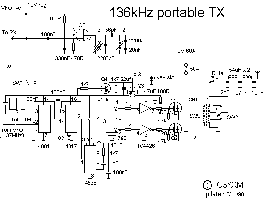
The diagram for the portable TX is below. It is built on the KISS principle so there's not much to it but it is capable of producing nearly 400W with the engine running! The constuctional details are in the article 136tx.doc which can be downloaded below.
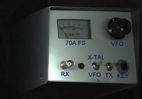
Here's a picture of the portable version. I've managed to fit it in a case 125mm wide x 95mm high x 210mm deep.
More photos of the /P version.
Download the article on the portable rig in Word2 format. (49k)
See bottom of page for zipped-up version and diagrams...
The base station version
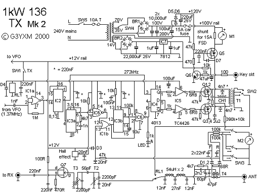
Using high voltage mosfets means that the power supply for a kilowatt amplifier becomes a bit more manageable. I started off with low voltage fets running at 20V but this required 60 Amps or more which meant everything was big! With an 80V rail we need only 15A to get a kilowatt as the switching design is so efficient. The fets used here are 500V rated so they can easily stand the 100V off-load voltage and no PSU regulation is required... More weight and heat saved. It is theoretically possible to get the full output with just a pair of fets but I have played a bit safe and used four. I have also added protection circuitry to cope with over current and mismatch, these refinements could be added to the portable version if desired, as the drive circuit is basically the same. In the version pictured I use a CB synth rather than a VFO, the black window on the right is the 7 segment "channel" display.
As you can see, the circuit is basically the same as the simple version but a few refinements have been added. I have not yet produced a PCB for the drive board but I may do one day. It can be built on strip-board in one evening.
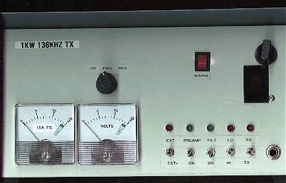
Here is the front view of my version. The inside is not so neat! The meters are not the Maplin ones given in the parts list but some 1mA ones I got at the Leicester show. I have added a row of idiot-lights to make it look more high-tech and added switching for external receive aerial, preamp and filter on/off etc.
Download the article on the base stn. version in word2 format. (169k)
See bottom of page for zipped-up version and diagrams...
Bits for both rigs
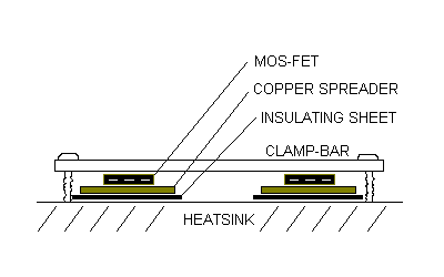
This is the mosfet clamping system pinched from the 160/80 linear. You don't need the copper heat spreaders for these rigs as the dissipation is not so great. When using four fets, I put some rubber cut from an old inner tube between the fets and the clamp-bar to equalise the pressure. Everthing else is a total bodge and it all works OK so there shouldn't be any particular layout problems. Just keep earth returns short and use good quality Cs and thick wire....

The VFO.
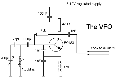
Not much need be said about this, I only include it for completeness. It's a Colpitts thing made of bits from the junk box. The capacitors around the tuned circuit and choke are polystyrene and the coil is wound on an old quarter-inch IFT former. The resistor values aren't critical.
It's all in a metal box with a reduction drive on the tuning C. Stability is very good because the final TX frequency is a tenth of the VFO frequency so the drift is ten times less. You can check it's working with a medium wave radio.
Crystal option..
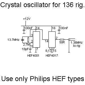
1.37MHz crystals are very expensive whereas 13.7MHz ones can be made for about £8 each. Another divide by ten chip does the required frequency reduction and the output is connected straight to the "VFO" input of the main circuit. If VFO facilities are not going to be required the output from pin 2 can be connected straight to pin 14 of the 4017 in the main rig cct.
It is very important to use Philips Locmos (HEF4XXX) chips in this part of the circuit as they are the only CMOS chips that go fast enough!
Or synth?
I am now using a CB rig synthesiser to give better stability in case anyone is using ultra-low bandwidth receivers. It's a Rotel RVC220 (useless piece of kit!) legal CB rig whose synth runs at half output-frequency. Unfortunately this is about 13.8MHz which, when divided by 100, puts it outside the top of the band. Replacing the 10.240MHz reference crystal with 10.075 MHz gives almost full coverage of the band in approximately 50Hz steps when divided down. I removed the TX components, strapped it onto TX and re-tuned the "doubler" stage in the TX strip to 13.6MHZ. This gave about 12V pk to pk which will just-about clock an HEF4017 decade counter (only this type seems to work at 13.7mHz... perhaps 74HC series would be better). The 1.36MHz from its' carry output is then fed into the TX divider strip as above. A DDS synth suitable for this design is shown on G0MRF's site at http://www.g0mrf.freeserve.co.uk/

Suggestions received....
A lot of your suggestions have gone into the current design that you see here, if you have any more let me know.
John G4GVC has had some problems with the 4001 squarer stage oscillating of its own accord with no drive applied, this defeats the logic which only works if the drive stops. A 470pf across the input terminal stopped it on another example.
Thanks to Rik ON7YD for the idea to simplify the interlock circuit by shutting-off the 4013.
A 73kHz version of the 12V rig is working fine, 8 turns on the output transformer and double the values of L and C in the tx filter.
Some have suggested that the lack of any "dead time" between the switch-off of one fet and the turn-on of the other is a bad idea. I pondered the idea of using SMPS controller chips which have this facility, to fire the mosfets but so far I haven't actually tried it. It could yield better efficiency and less harmonics.
The latest version of the 1kw TX uses a series transistor for the keying function. This gives better keying envelope and less key clicks.
Any good ideas? Let me know and I'll try them and/or publish them here.
 Top view
 Side view
 Typical driver board.