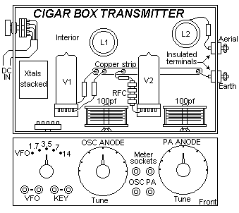


It is customary for newcomers to amateur radio to think in terms of Hammerlund, Hallicrafter and similar receivers and tramsmitters of 100 watts upwards, complete with lines of meters. V.F.O.s and a whole load of other gear; a laudable aim, but not one particularly realisable in these days of short pockets and long prices. As regards the fellow living in the country, even if he is in a position to spend a fair amount of cash on his hobby, all too often he is without electrical power and the cost of operating a normal amateur station from batteries is completely prohibitive-for any ordinary individual, anyway. For the city fellow with little cash, the countryman with no mains, or either of them with little room for a full-sized den of their own, the cigar box transmitter, then is really the answer to a prayer. It will provide a lot of fun at small cost and when the user has finished his "ragchew" on the band, he can close the lid and put the transmitter away in a bureau drawer until the next time! The power, of course, is in relation to the size of the rig; in other words, it is very low, 1 watt to be precise. But if you imagine that 1 watt will not get you anywhere at all, just give this little transmitter a try and you will find that it is quite possible to work DX, even with 1 watt. Given a decent aerial, of course, and having a little regard for the times when the bands are less congested than in the evening or Saturday afternoon.
The arrangement is conventional, crystal oscillator and power amplifier both valves being standard 1S4 types. Switching is provided for the crystals, the rig operating on fundamental frequencies on the 1.7, 3.5 and 7 Mc/s bands, while doubling is used for 14 Mc/s. It is felt that there is not much point in making the transmitter available for 28 Mc/s, but this can be done if the user wishes, and the coil data for this band will be furnished on request. In addition to the crystals, provision for VFO operation is made by a further contact on the selector switch, enabling the VFO to be switched in at will. Metering, too is very simple, a 100mA meter, which can be plugged into sockets on the front of the box, permitting all necessary circuits to be checked and tuned for resonance. Al components, wherever possible, are miniature types and so indicated in the component list. Obviously the components should be obtained first, and the cabinet made or obtained to suit.
The station is solely intended for code work as it stands, keying being carried out in the negative HT circuit of the oscillator valve. The theoretical diagram is given above and the layout is below.

The batteries, naturally are not included in the cigar box case; that would be asking too much. However, as originally planned and constructed, a simple three-valve TRF receiver, using miniature valves, occupied one half of the case and the transmitter the other half. It is felt that readers would not be greatly interested in the receiver and would probably prefer to use one they already own or to build one to their own design rather than attempt to build both receiver and transmitter into such a small case. Nevertheless, if readers express interest in the receiver too, all pertinent details will be given at a later date.
The coil data is given on page 149 (after this text - Harry) for all bands in common use. When these coils have been wound and the little transmitter assembled and its wiring checked it should be attached to a half-wave end-fed aerial of 66ft. in length, and the 7 Mc/s crystal switched into circuit. The meter should be plugged into the sockets in the anode circuit of the oscillator valve, and the circuit tuned to resonance by means of the variable condenser in the circuit. This will be indicated by a "dip" in the anode current as shown on the meter, in other words a reduction in the anode current. The meter should then be removed and the socket shorted together with a "U" link, two plugs joined by a sturdy piece of wire. The same procedure should then be gone through with the power amplifier, then the transmitter is ready to go on 7 Mc/s. Naturally it will be necessary to tune in this way whenever the frequency is changed, but the procedure takes only a minute or two at most.
Provided the components are bought judiciously - and many of them can be obtained at surplus dealers - the cost of this transmitter will be very small and the subsequent enjoyment out of all proprtion to the time and cost involved in the construction. One can hardly say more of any transmitter, however powerful and expensive it may be.
Coil winding
1.7MHz, L1=50turns, 1.75"long, L2 is as L1 with tap at 18turns.
3.5MHz, L1=28turns, 1.5" long, L2 is as L1 with tap at 8turns.
7.0MHz, L1=14turns, 1.25"long, L2 is as L1 with tap at 5turns.
14 MHz, L1=8 turns, 1.5" long, L2 is as L1 with tap at 3turns.
All coils are wound with 20 S.W.G. enamelled wire. Winding length is given in inches. All formers are 1-1/2 inches in diameter.
* = Tap may have to be adjusted to ensure good loading.
Components
Xtals for 1.7, 3.5 & 7 Mc/s
1 - Single pole 4-way switch
1 - 3-pole 2-way switch
2 - 2 valve holders
2 - 1S4 valves
1 - 100mA moving coil meter
3 - 0.01uf fixed condensers
1 - 0.05uf fixed condenser
1 - 150pf fixed condenser
1 - 3 Henry R.F. choke
1 - 100pf variable condensers
6 - Banana sockets
4 - Banana plugs
Resistors as as in drawing
Have fun, de HARRY, Lunda, Sweden.