
I keep receiving E-Mail from people who are not happy with the basic "Frequency Modulation Wireless Microphone" (BUG) transmitter because:
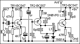
So, without further ado, here is another FM Wireless Microphone with added microphone amplifier and power amplifier stage to increase the microphone sensitivity and range. Please note that this circuit is drawn from memory and I cannot guarantee that it will work well without some form of modification so please treat this project only as an idea. I had loads of success with this version of the circuit in the early 80s and had a range of about 2Km. I will build this version again later, after my present projects are complete, then present any possible changes to the circuit.
There is no PCB available for this idea, yet.

Note that "BUGS" are illegal but "Wide-Band Frequency Modulation Wireless Microphones" (WBFMWMs) are not, as so many people have told me (including the RSGB!). This project may well be illegal but this is up to you to investigate.
Some screening is required between TR2/L1 and TR3/L2 to prevent the possibility of spurious oscillations. The coils should each be about 6 turns of wire with a tapping somewhere between half and one turn from the 'cold' end.
GETTING IT WORKING
You may want to replace the 6.8pf (6p8) capacitors with 10pf variable trimmer
capacitors. Set the oscillator capacitor for the frequency you want then adjust
the amplifier capacitor for a minimum DC voltage accross the 47 ohm resistor in
the emitter of TR3. If you stick to fixed capacitors then adjust the number of turns
on the oscillator coil L1 for the frequency you want, squeeze/stretch the coil for
fine tuning. Duplicate the coil for L2 and squeeze/stretch the coil for a minimum
voltage accross the 47 ohm resistor in the emitter of TR3.
You may want to try to increase the output power a little, change the 330 ohm resistor in the emitter of TR2 for a slightly lower value. Do not use less than 100 ohms if you want TR2 to survive. If you still want more power then drop the value of the 47 ohm emitter resistor in TR3 and replace TR3 for a higher power device, such as the 2N4427, BLY33, 2N3866 etc.
If it does not work then re-check the wiring, especially the orientation of the transistors. The collector of TR1 should be about +6 volts w.r.t. ground. If not then adjust the value of the 4K7 emitter resistor in TR1. Short circuit L1 with a screwdriver and check that the battery current varies. If not then check the capacitor connections and values. Adjust the tapping on L1 for the maximum DC voltage accross the 47 ohm resistor in the emitter of TR3. If the modulation is too loud then you will hear distortion if you speak too close to the microphone. Remove the 1uf capacitor from the emitter of TR1.
After all this you should have a WBFMWM that will make MI6 envious. Just don't get caught with it in the boss's office - you have been warned! You will also need a stock of batteries if you intend using it for any length of time. To get more power out you will need to put more power in.
Have fun, de HARRY.