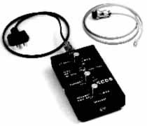

Basic Countermeasures Equipment

SCD5 - CARRIER-CURRENT/SUB CARRIER DETECTOR
Stand-alone unit covers 10 to 700KHz. Designed to detect presence of carrier current transmitters on AC or telephone lines or subcarrier signals. Unit is powered by two standard 9-volt batteries and is supplied with detector/amplifier, AC input cable, telephone input cable, headset, instructions and carrying case.
The battery powered SCD5 is designed to detect VLF (10 KHz to 700 KHz) carrier-current signals on AC power or telephone lines. The unit is supplied with detector/amplifier assembly, AC and telephone input cables (both protected to 400 volts DC or 50/60 Hz AC) and headset.
TO OPERATE: Connect the appropriate cable to the input jack. Insert the headset. Set the band selector switch to the 100-700 KHz range. Set the RF GAIN and TUNING controls at 12 o'clock. Turn the SCD5 on by rotating the VOLUME control slightly clockwise. The red PWR (power) indicator will light. Advance this control until a slight background hiss is heard. Slowly rotate the TUNING control through its range, i.e. LO to HI or visa versa. If a signal is detected, the unit will lock at several points on the dial. Once locked, turn the VOLUME control further clockwise and listen to the signal. Use the same procedure to listen through the 10 KHz to 100 KHz band. Remember to turn the unit OFF when tests are complete!
Under some conditions it may be necessary to increase or decrease the setting of the RF GAIN control. Operating experience will determine the best position for this control.
The SCD5 is powered by two Alkaline 9 volt batteries. Zinc-carbon batteries can not supply enough current to run the SCD5 for any length of time, but may be briefly used if Alkaline batteries are not available. To replace the batteries, loosen the cover screws on the sides of the unit one or two turns counterclockwise. Carefully remove the back cover. Note the position of the batteries. Remove the old batteries and replace with fresh ones (in the same position). Replace the cover and tighten the cover screws (don't over-tighten).
As with any piece of battery operated equipment, remove the batteries during periods of prolonged storage.
![]()
Any comments or questions regarding this specific page?
Please feel free to sign our Guest Book
![]()
|
To be contacted for a confidential consultation please E-mail: jmatk@tscm.com
or send a letter via US Mail to:
or call:
URL: http://www.tscm.com/ |