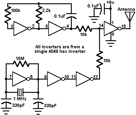


This circuit uses a 4049 hex inverter to form an AM radio tone transmitter. The RF oscillator in this circuit uses one inverter; its frequency is controlled by a 1 MHz microprocessor crystal. Two more inverters amplify its output. Meanwhile, the two inverters at the top left produce an audio tone, which is modulated onto the RF signal by the last inverter. You can tune this in as an audible whine at 1000 kHz on your AM dial. A few inches of wire attached to the output terminal should suffice as a transmitting antenna. This circuit also has another use. It emits harmonics at all whole-number multiples of 1 MHz (i.e. 2 MHz, 3MHz, etc., up to at least 10 MHz) and you can use it to check the dial calibration of a shortwave radio.
Source: "Electronics Now" Magazine, Jun, 95 issue. (C) Copyright Gernsback Publications, Inc. 1995
Home | Product Info | Ordering Info | Contact Us | Get a Demo
Circuits in CyberCircuit | Circuits in CyberCircuit Plus | Circuit du Jour | Circuit Archive
Copyright (c) 1995-1998 by PTM