
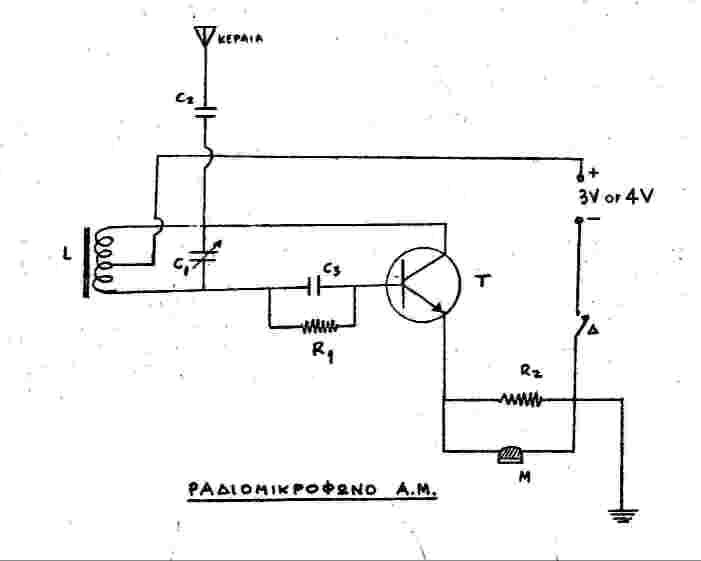
diag. 1 (PNP type tranzistor)
Hello,
Since many people are looking for low power radio
transmitter plans, Ive decided to post the plan of the most simple radio
transmitter I know. It is a little AM «bug», a wireless microphone
really, for the Medium Wave band (but it can be used for low power broadcast
on the Short Wave band to).
What is attractive in this circuit is its simplicity.You
cant expect much from such a little project, but, its a good and
especially easy start with low power broadcasting. It won't cost
more than 5-10 USD, the components are everywhere readily available (or,
they can be canibalized from any old AM portable radio). It can be constructed
and tested in less than 2 hours.
diag. 1 (PNP type tranzistor)
Description
The transmitting power is subject to the transistor type
one will use and the voltage of power supply, but its somewhere around
50mW, as far as I can tell.
I found that my construction works best on the 800-1200
kHz range, but with changes to the inductor L or the variable capacitor
C1 it can transmit to the whole range of the AM dial.
The range depends mainly on antenna length and grounding.
With a simple 75cm telescopic antenna (or just a short wire) and no grounding,
its between 20-50m. With a full L/4 single wire antenna and good grounding
the signal can be heard several hundred of metres away on an ordinary radio
- 300-500m most likely - even further with better radios. Not much, but
with that range it can reach many people in an densely populated urban
are, or as in my case it can cover a whole village.
The audio fidelity one gets from this little transmitter
is good for AM standards.I mean that.
The current from the power supply is subject to transistor
type and the voltage and is between 1-6mA, very low indeed! Running it
from a battery (3-4.5V) it will work for a long time before the battery
is exhausted.
Construction
It can be constructed with only 7 components. One transistor
(T), two resistors (R1 & R2), three capacitors (C1, C2 & C3) and
an inductor (L). The transistor can be of any type. In the above diagram
(diag.1) its an PNP transistor but one can use an NPN transistor (as in
diag.3) but notice that in this case the polarity of the power supply (battery
etc.) is reversed.
There is no need for a Printed Circuit Board (PCB), though
if you want you can use one (see diag.2), it is always giving better result
with RF projects.
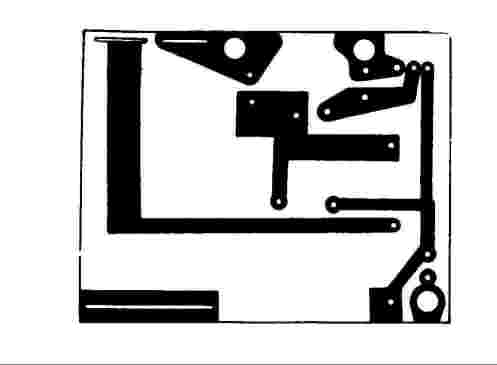
diag. 2 Printed Circuit Board (optional)
Component list
R1= 100 KOhm 1/2W
R2= 500 Ohm 1/2W
C1= 50-350 pF variable capacitor
C2= 250 pF
C3= 150 pF
T= AF 126 (but also AF 127, AF 139, 2G108/109 or any
equivalent)
L= 66 turns of 0.35mm enameled wire around a 8X140mm
ferrite rod with a connection point made at the 33rd turn
(M= Its an optional «charcoal» microphone
(like those used in telephone sets a few years ago). Instead, you can put
there a headphone jack and feed the transmitter with audio from an audio
mixer/a stereo unit/CD/cassette player, or whatever audio source you wish...)
The transistor (T) can be of any type. It doesnt even
need to be a high frequency one. I've used so far the AF 126 and AF 127
(AF 139) PNP type both, and the NPN type AC 127. Any low power PNP type
(like the AF126, AF127, AF139, 2G108, 2G109 etc.) will do. If you use an
NPN transistor like my AC 127 (or the 2N1711, 2N708, 2N930, 2N1893, BC170
etc. ... or any equivalent) youll have to be careful with the polarity
of the power supply.
diag. 3 (NPN type tranzistor)
Component variations
Ive used a 1000 ohm resistor as R2 (instead of 500 ohm).
I dont remember why I did that but the unit works OK as is.
Sometimes instead of the variable capacitor of 50-350
pF as C1 I use a fixed 150pF ceramic capacitor. With that the transmitting
frequency is around 850-855 kHz but the stability suffers a bit.
The ferrite rod I currently use is just 8cm long (because
the, very fragile, original 14X0.8cm broke to pieces, I used the bigger
fragment). I believe that a longer ferrite rod can increase the range somewhat.
I initially used as T an AF 126 transistor with a power
voltage of 3-4.5V. I fed it with more voltage to increase the range, but
it finally blew after working sometime at 9V. (Tip: dont use more than
4,5 V as a power supply with the above PNP transistors, or you are going
to blew them. If you do want to experiment with higher voltages - up to
9V/12V - have some spare transistors at hand and prepare to use them).
I later used the AF 127 (2G type) instead. With that,
the range was a bit reduced, and they were too sensitive to voltage increases:
dont use more than 6V with those (but feel free to experiment with higher
voltages -7.5/9V - only dont forget those spares!). With more than 6V
this transistor is overheated, so a heatsink can save it, for sometime,
with 7.5 or 9V.
The NPN I currently use, the AC127, its absolutely immune
to higher voltages. In fact with less than 9V the range is very limited
(just a few metres), but with 12V or more (I use an 18V power supply at
the moment, for best results).
My next project will be to increase the voltage to 24V
and even 35V if the transistor survives! Only, I dont have a spare AC127,
so I wont try anything until I get a couple. I believe that (with a decent
antenna) 24V will give me an effective range of 1 Km and even more with
35V.
I also plan to use a 2N3055 tranzistor and see what happens!
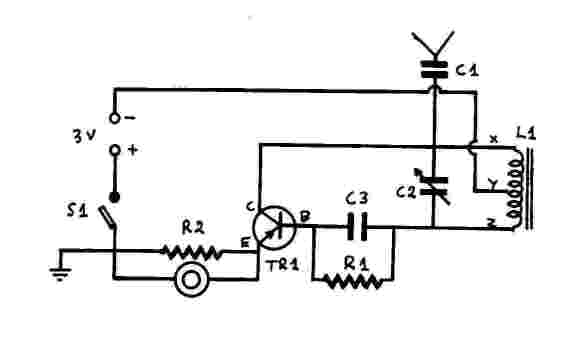
diag. 4 (A variation of the plan with PNP tranzistor,
C2=C1 and C1=C2 in the component list)
Other Possible modifications (Havent tried them myself
except #1)
There are a number of possible modifications that can
improve the performance of this little transmitter.
1. You can use an electrolytic capacitor 25-50 microF/25V
at the input of the power supply to eliminate any interference (50/60 Hz
"hum") from the power supply, if you are on mains (no need for that when
using a battery).
2. A matching transformer like that old AD9014 or any
equivalent, at the input of the Audio feed might improve further the audio
fidelity, though as I said above its already good enough as it is.
3. The use of a power transistor with a heatsink
as transistor T will definitely improve the range, as it will allow higher
voltages.
4. I think that a lengthier ferrite rod (one about
19cm long) will also improve the radiating power and, hence, the range.
Adjustments
When your construction is finished earth (ground) the
unit, connect the antenna, switch on your audio source, tune an AM radio
on a clear channel between 800-1200 kHz, make sure that the polarity of
the power supply to the transmitter is the right one and then switch on
the transmitter. Adjust the C1 var. capacitor until you find the your signal
on the radio.
Performance and Use
If battery operated, with the simple «charcoal»
microphone as an audio source (as in the diagrams), and a short (50cm or
so) helical wounded wire for an antenna this little unit can be used as
a «wireless microphone» with a range between 5-15m. A 75cm
telescopic antenna is better if someone want to use them as AM walkie talkies
along with small portable AM radios. The construction can be put inside
an emptied plastic 4.5V torch case for such a use. The range will be somewhere
between 20-100m.
If used for low power broadcasts instead of a microphone,
connect the unit to the phone jack of a stereo unit, an audio mixer or
a PC sound card(!). I obtained best results when taking the audio feed
directly form the loudspeaker wires of my home stereo unit, but from a
«line out» or a «phone» output jacks the results
are quite similar. Use a longer antenna if you want to be heard in some
distance.
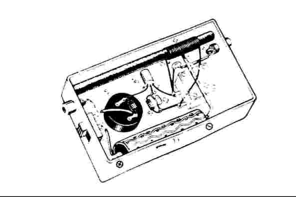
pic. 1 (possible constuction, sorry for the quality of
the pic, I'll try to upload a better one asap)
Antennas and Grounding
AM transmitters require long antennas and good grounding
to perform at their best. If you want maximum performance use an L/4 single
wire antenna, calculated to your desired frequency (i.e. the antenna length
(ANT) should be equal to the Wavelength of the desired frequency (L) divided
by 4). A 5/16 wavelength antenna might be even better but it will be more
lengthy. You can calculate the particular wave length (L) of any given
frequency (f) if you divide the light speed C in metres (300 * 10^6 m/sec)
with the frequency f in Hertz. Practically 300/F in MHz will give you the
wavelength in metres.
Example: If your chosen frequency is 1250 kHz then, Wavelength
L=300/1.250=240 metres. Thus the optimal antenna length (ANT) in that case
will be ANT=L/4=240/4=60 metres of 0.3-1mm single strand wire, usually
suspended with insulators between two buildings, or trees (except if you
live on a building 60m tall. In that (unlikely) case, just hang down the
wire out of your window, to have a true 60m vertical antenna!)
Grounding must also be good for best results. There are
several simple ways to «earth» your transmitter.
One way is to connect it with a lead to a metallic water
pipe or a tap. Another is to connect it with the «ground» of
an electrical socket but avoid that option, especialy, if you are unfamiliar
with electrical wiring. Mains voltage can kill. A third way is to take
a wire from your transmitters ground and connect it to a single or a number
of metallic rods stuck in - preferably moisturized - soil.
For those perfectionists out there, there are more elaborate
(much more effective) ways to earth their TX units. Grounding frames, grounding
radials etc. A number of ground radials of L/4 length (2,4,6...16 etc.)
is one such a way, but if you take the trouble to construct such a grounding
system, do yourself a favor and get a more powerful transmitter!
For more info on AM/MW antennas see related web sites.
Range
That's the most important aspect in transmitters, is
it not?
Well, as I said, dont expect much from such a simple
transmitter. To get the maximum out of it, experiment with the higher voltage
possible for the transistor you are using and use an appropriate antenna
for your chosen frequency.
The chart below will give you an idea from my experience
(«L/4 ant» is the optimal antenna length for the chosen frequency,
and «antenna» is the actual antenna length I used. In the AF126
case the 6m antenna was of 1mm braided insulated wire. In all other cases
was of 0.3 single stranded insulated wire).
| TR type | Voltage (DC) | Current | Power | Freq | Wavelength | L/4 ant | antenna | range (MW) | range (SW harmonic |
| AC127 | 18V | 6mA | ~50mW | 1215 kHz | 247 | 61.75m | 30m | 250m | |
| AC127 | 18V | 6mA | ~50mW | 1250 kHz | 240m | 60m | 15m | 150m | 200m 3750 khz |
| AF127 | 6V | ~4mA | ~15mW | 1080 kHz | 278m | 70m | 6m | 50m | 100m 9720khz |
| AF127 | 4.5V | ~3mA | ~10mW | 1080 kHz | 278m | 70m | 2m | 20m | 50m 9720khz |
| AF127 | 3V | 1080 kHz | 278m | 70m | 6m | 20m | 50m 9720khz | ||
| AF127 | 3V | 1080 kHz | 278m | 70m | 2m | 5-10m | 20m 9720khz | ||
| AF126 | 9V | ~1200 kHz | 250m | 62.5m | 6m | 100m | |||
I estimate that an AC127 with 18V at 1250-1251 kHz with a 60m antenna will have an effective range of 500m (for reception with an ordinary portable AM radio) or 700m (for better AM receivers).
Problems
Not any particular problems will occur with this transmitter.
Attention should be paid to the careful construction of the inductor L,
to the right connection of the transistor legs and the battery polarity.
If there is "hum" in the audio, check your mains adaptor, choose a grounded
one to avoid the "hum".
Sometimes, when I use a portable CD player for audio
source odd things happen. The CD disk stops or starts going backwards.
To avoid such problems I connect the CD player to an Amplifier and take
the audio from there, however I haven't been able to resolve the problem
permanently. My solution some times works an other times fails.
pic. 2 (the coil for the inductor L).
Interference
No annoying spurious signals are likely to be detected
in other positions of the AM dial. In my experience even on a radio sitting
just next to the operating transmitter only a couple of a faint signals
can be detected few 100s kHz above and below my chosen frequency, and those
disappear completely 2-3 metres away from the transmitter. So it is unlikely
that any neighbors trying to listen to their favorite AM station will complain
for interference from you if you choose an unoccupied channel to transmit.
Splatter is also unlikely to cause interference to adjacent
channel reception for more than a few metres from the unit, but if someone
nearby is trying to listen to Short wave, well there might be a problem
because of harmonics...
Harmonics
Harmonics are inevitable and this transmitter is no exception.
In fact this little goblin is a true kindegarden for harmonics!
Ive found out that some of the harmonics produced can
be received from greater distances than those in the basic frequency. So,
if you are going to use this transmitter in a highly populated area (especialy
in the night hours) use a low pass filter to filter out the harmonics because
it can cause interference to Short Wave reception. The 3rd harmonic and
oddly the 9th seem to be the more powerful ones.
There are also sub-harmonics that can be received on
the Long wave band. When transmitting somewhere between 1300-1400 kHz I
also received my signal on Long wave 320-340 kHz.
Odd behavior: A bonus?
When setting the transmitting frequency to 1080 kHz I
found out that the 9th harmonic at 9720 kHz on Short wave was so powerful
that it could be received in distances 3 times greater (150-300m and more!)
than the MW signal in 1080 kHz (50-100m), (6 to 15m antenna scenario).
I dont know why this happens with this harmonic but one might consider
it an additional bonus if one wants to transmit on the SW band. In that
case just calculate your antenna for the 31m band and your signal will
be heard much further than the MW!
The same applies for the Long wave sub-harmonics. Use
an appropriate antenna for LW and broadcast in the LW band if you weirdly
desire so!
However if you just want to transmit on MW do filter
your signal in order to avoid causing troubles to nearby DXers who try
to log on a distant LW or SW station just where your harmonics are.
X-Radio Files
Strange things have occurred during my experiments with
this transmitter (TX).
If switched on and no audio fed to it I could turn the
C1 knob and hear in the radio, coming through my transmitter (?!), on my
preset frequency other AM radio stations with their signals amplified!
It was working as a AM/RF amplifier & tuner!?
But the most weird thing happened when, once, I
switched on the audio before switching on the transmitter. Even though
the transmitter was switched off, the audio was heard from the radio, weak
but audible! Startled I checked the power source and confirmed that it
was disconnected indeed! Ghost transmissions? Well, I figured out that
the electrolytic capacitor I was using to filter out the 50Hz mains interference
was discharging slowly and was behaving as a battery! As the current going
through this transmitter could be as low as 1mA, even a charged electrolytic
capacitor could emulate a battery!!!
Summary of transmitter characteristics
| Characteristic | Recommended | Possible |
| Modulation type | AM | Transmissions on the LW, MW, SW bands are feasible with none... |
| Frequency range | 700-1600 kHz (actual) | ... or only minor modifications to the LC tank and/or the antenna |
| Working voltage | 3-4 VDC (AF126/127 case) | tested up to 18V (with AC127, depends on tranzistor type) |
| Maximum current | 6mA | 0.3-10mA (depends on tranzistor type) |
| Output power | 50mW | ranges from 10 to more than 50 mW |
| Audio fidelity | good for 9kHz channels | better in the case of 10kHz channels |
| Stability | good | is affected by the quality of the C1 var. capasitor |
| Range | 150m max with 1/10 antenna | more than 500m with a full L/4 0.3-1mm single stranded wire antenna |
Final comments
Perhaps that was a too exhaustive article for such an
insignificant AM transmitter. However many things included here also apply
to better and more powerful AM transmitters. And one can gain useful «broadcasting»
experience with it before moving on to higher powers!
I first saw the diagram of this little transmitter in
a, Greek, primary school circulated magazine, in 1975, when I was 10. I
was immediately hooked to it and started having dreams about making my
own broadcasts. Ultimately that incident directed me to electronics, so
when I grew up I became an electronics technician. However, I finally managed
to get «On Air», as «FM Radio Corsair», four years
latter, in 1979 but on the FM band (the FM audio quality is far more attracting
to youngsters, there is no AM Stereo in Europe). My first 2 transistor
low power FM transmitter had a range of 500m and was upgraded in 1981 to
a single EL 504 tube operated FM transmitter (10-15W) which gave me an
average range of 10km (though reception reports from 25km and even 75 km
were coming from time to time). My radio days went on as «FM Radio
Corsair» in my home city of Thessalonica, in Macedonia, Greece for
the 1981-1985 period. As those radio days where approaching to their end
in 1986, I remembered that little AM radio-microphone of my childhood days
and decided to build it just to have the pleasure of hearing my voice on
the MW/AM band too. The results of that project are described in the above
article.
Recently I was asked to organize an FM radio station
for a local municipality and my interest in radio (which remained limited
to DXing since 1987 was renewed. So apart from the «serious»
FM stuff, I dig out that little AM «bug», with its AF 126
transistor «burned». I quickly replace it with an AF 127 (and
later with the present AC 127 when all my three AFs where sacrificed to
experiments), an I was «playing» with the airwaves again on
the AM dial!!!
Note: Greece is a showcase of how «free» radio
once has achieved its goal for «legalization» can degenerate
to commercial exploitation. FM radio is «free» - only, read
here «commercial»/private - but, not so low power, broadcasting
on the FM band is open to anyone under some reasonable minimal conditions.
Private AM broadcasting is officially illegal, though, low power AM transmissions
from «bugs» are «de facto» tolerated. No one will
bother a low power AM radio station that causes no interference to anyone.
In fact, even though there is a radio-regulating authority, I havent heard
of any radio policing «authority» - if one still exists! -
bothering, even the few high power AM radio «pirates», in recent
years. Thats probably due to the fact that AM stations have a very limited
audience nowadays. Perhaps their limited appeal is not seeing as threatening
the «system» anymore!
Regards ... and best wishes if you decide to build the
little AM transmitter I have described...
Christos Z. Konstas
For FM stuff go to
former operator of «FM radio Corsair» in
Thessalonica, Macedonia-Greece
send comments at alt.radio.pirate
or at:
granazis@hotmail.com
to my Free Radio pages
http://www.freeyellow.com/members7/gearloose/free.htm my new Free Radio home age. http://www.freeyellow.com/members7/gearloose/part15.htm Part 15 broadcasting tips. http://www.freeyellow.com/members7/gearloose/start.htm A beginners guide.
PS.1 Lighting Warning!
As I was finishing this article a lighting stoke my newly
installed 30m wire antenna, while the transmitter was switched on. I did
have a little warning, a couple of seconds before the strike the audio
was coming with static crackles to my monitor radio. When I realized what
was happenning I tried to switch off the transmitter but it was to late
for it. My precious AC 127 (maybe along with other components too) was
destroyed. As I live in a very isolated area, an island out of the main
shipping lanes, I'll be off the "Air" :-( for some time, until I receive
some replacement tranzistors.
So, the lesson is: Don't take lightly the lightings!!!
PS.2 Also remember that if you break any law or if anything
bad happens to you while you try to assemble, or operate this AM transmitter,
I'm not responcible.
For FM stuff go to
http://www.freeyellow.com/members7/gearloose/fmtx.htm
![]()
|
|
|
|
|
|
| This site is hosted for FREE on FreeYellow -- yours can be, too! Click here for more information. | |