two stage VHF TV sound receiver with super re generative detector***
sub subject: Super re generative detector can detect FM modulation by slope detector****
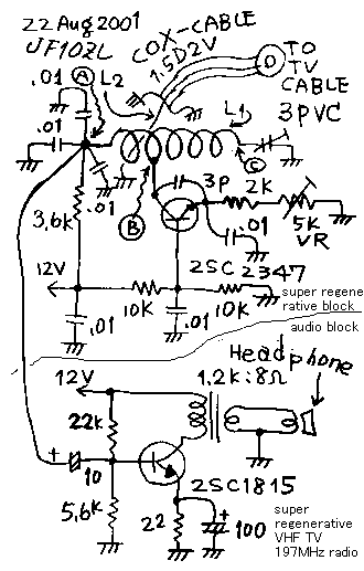
srvr1.gif....circuit diagram of this gear
 L1:
1.2mm diameter , 6 turn around redpencil 10mm doameter.
L1:
1.2mm diameter , 6 turn around redpencil 10mm doameter.L2 : 20mm long , 1.2mm doa wire
2SC2347: maker= toshiba: usage=UHF OSC/VHF MIX: Vcbo=30V: Pc=250mW: hfe=20 or more: ft=650MHz: Cob=1.5pf
2SC1815: maker= toshiba: usage=Low frequency AMP: Vcbo=60V: Pc=400mW: hfe=70 to 700: ft=80MHz: Cob=3.5pf
When I was about 13 years old. I bought several junk boards of 27MHz toy super re generative transceiver. It priced only 50 yen (half dollar) by one board. I repaired them and made QSO with my brother with these transceivers. After I became a radio amateur, I have never touched to the super re generative receiver until now. But for only experiment, I made this TV sound receiver and it worked well today. I make it sure that the super re generative detector can detect the wide modulated frequency modulation signal by the slope detection. ***
How to make coil***
Prepare the 1.2mm diameter nickel covered copper wire. Wind it 6 turn around red pencil. Cut the wire. Pull it to make a shape of suspension coil of motor vehicle. It is L1 of the figure. By the way, solder three capacitors parallel on the ground board. Solder the one tip of the L1 coil on the capacitor. It is A point of the figure. Solder the hot end of the patting trimmer 3pF on the another side of L1. It is indicated as C point of the figure. Make loose link L2 with 20mm wire and attach it the coaxial wire. 1.5D2V is the number of the coaxial cable defined in Japanese standard. Be care L2 do not touch to L1 directly, because L2 has no DC voltage but L1 has DC voltage. Be care all the lead wire of the parts used on super regenerative circuit should be less than 5mm long. Especially the lead of collector of the transistor as B point indicated on the figure should be short. ***
Choice of the transistor***
Please choose the transistor on the super regenerative circuit from the type it is recommended for VHF oscillator or mixer by the transistor manufacturer. This transistor should have 1GHz or more for it's ft. 2SC2347 is famous in Japan as this usage. ***
After connect the antenna cable of my house, I could hear the 8th channel sound program with small volume ,by tuning trimmer and variable resister. The sound of 8th channel in Japan is 197.75MHz. If you live in out of Japan , please make this gear with the frequency in your country. With this gear the quenching noise was very small different from my image standing on the experience of 27MHz transceiver. It may be by the reason of difference of the frequency. But I have no material to measure the pulse such a high frequency. The high frequency wave energy radiated by this gear is very small and it made no interference for the another TV set in my house.
Description add on 30Aug2001: prototype of super regenerative FET - VHF FM receiver***
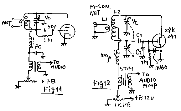
As a next step of super regenerative receiver using transistor , I decided to try to make it with FET. When I made the transistor type , I could use the circuit introduced on old book as tree transistor super regenerative transceiver. But I have no information about that with FET. So I decided to try based on the super regenerative circuit with triode tube. Please see the Fig11. From Fig11 I developed the circuit Fig 12. And with the circuit of Fig12 and audio amplifier, the same thing with upper last model, I can here FM broadcasting signal.
srvr11.gif

Explanation about the parts
*** Antenna connector is M- type connector. I used 14MHz dipole as a part time antenna.
*** L1= 0.8mm enamel wire 2 turn on 10 mm diameter
*** L2= 0.8mm enamel wire 9 turn on 10 mm diameter, with center tap.
*** VC= air variable capacitor made for FM receiver, 50p tree stage . I use two of it
*** 1N60 = world most famous germanium diode
*** 2SK241: maker= Toshiba. Usage = VHF/AMP. Type =Mos. Idss=1.5 to 14mA. Vgs(off)mx=-2.5V: gm=max10S: Cis=3pF typical : Crs=0.035pF typical: Power gain=28dB typical on 10MHz : 100 micro henry = micro inductor :
*** ST-91 is input transformer designer for input transformer to be used on push pull amplifier .On this figure 1st side is 400 ohms and the second side is 900 ohms, while it was designed counter side originally.
*** 1k is potentiometer
*** Audio amplifier is the same it of upper one.
*** All parts are connected directry on the non printed copper board. You say it as " ugry structure" , dont you?
Explanation about the action
**** On the old text book of the receiver, they say that this figure 11 is a oscillator. But different from the normal oscillator, the grid leak resister , indicated as 5M ohms on fig11, is very high impedance. So the grid keeps (saves) the oscillating electricity, and when it becomes plus , the grid current flows and grid becomes low impedance, and the high frequency oscillation stops. Therefore the quenching oscillation is achieved. In Japan it is well known that instead of grid current we should use germanium diode between the gate and the souse of FET. It is not my idea. I can make it sure that this method is effective. Without this diode the quenching oscillation has not achieved. And, with this diode it was done. *** With this circuit and the simple one transistor audio amplifier, by connecting the part time antenna , I can hear the FM broad casting of 78 to 79.5MHz. I could construct the FM UHF receiver only with two transistor. But is has the following weak points.
*** 1. When I receiver the local AM signal , the quenching noise was disappeared. But in this case , when I received the weak far FM signal, the quenching noise was not disappeared. While the FM broadcasting program is full of musical contents, I must hear that with many noise.
*** 2. This circuit detect the FM signal by the " Slope detection". Therefore I could receive the same signal on the two each point of the angle of the shaft of the variable capacitor. Therefore I feel that it is difficult to mark the frequency even if I attach the panel board between the variable capacitor and the knob.
*** 3. When I rotate the variable capacitor to change the receiving frequency, I have to tune the 1k ohm potensio meter to tune the strength of the oscillation. Therefore it needs a lot of time to change the receiving frequency.
*** 4. As the description of the upper, the changing of the receiving frequency make the influence to the regenerative strength. And I could use only a part of the angle of the variable capacitor as it*s controllable width, even with the re tune of the potensio meter. I could make it sure that " The frequency change ability of the super regenerative receiver is very narrow. It is only several percent."
*** Such a way, this prototype gear was not achieved so much effect. But I want you to understand the behavior of the super regenerative detector.
At last of this page
*** I report you that I receiver the compliant of TVI by my wife while the tuning of this gear. Please make care about the TVI , when you test this circuit. Thank you.
超再生2石式超短波TV音声受信機***
副題:超再生のスロープ検波でFMワイド変調が復調できるという噂(うわさ)は本当だった。

たった2石でテレビが受信できます。回路図に示した受信機で、テレビの8チャンネルの「サンマのなんとか物語」とかいう、極めていかがわしい、タレント馬鹿騒ぎ番組が受信できました。我が家の6エレ矢木アンテナに、この自作の受信機をつなげた結果が、こんな低俗な番組なので、がっかりです。気を取り直してご報告いたします。受信機は、まずスピーカーから近い所から作ります。回路図の下半分、低周波増幅器は、普通のトランス出力増幅器で電圧利得は実測24dBでした。回路図の上半分の高周波検波回路は超再生回路です。この回路は私が子供の頃によく27MHzの子供用おもちゃトランシバー等に使われていた回路です。何も、交信相手が電波を出していない時は、やたらとシャーシャーいっていて、いざ交信相手が入感すると、きれいに聞こえ出す変な特性(スケルチトランシーバーの逆)が印象的でした。私的には、アマチュア無線を初めてからは、超再生検波回路とは縁を切って、ひたすら清く正しいスーパーヘテロダイン技術に傾倒してきました。しかし、古い物の本には「超再生検波を使えば簡単にVHFの受信が可能で、しかも、FMもスロープ検波で復調ができる。」と 書いてありますので、これを実験してみました。
構造上の注意:コイルの製作1.2mm径のニッケルメッキ線を用意します。これを、赤鉛筆の周りにグルグルト6回巻いて両端を切ります。これが図のL1になります。一方、ベタアースの上に3個コンデンサーをならべて並列に片方をアースにはんだ付けしておき、ここにコイルのコールドエンド(回路図の(A)点)を付けます。コイルの反対側がホットエンドになるので、ここにパッティングコンデンサー(図の3PVC)の回転軸でないほうをはんだ付けし(図の(C)点)、パッティングコンデンサーの軸につなかっている方をベタアースに付けます。この時、コイルの形はいいかげんでOK。密着巻きでなく自動車のサスペンション程度に広げます。別の線を20mmの長さに切って先ほどのコイルの螺旋の中を図の様な感じで通るようにして、片方をアースに付けて、反対側を同軸ケーブルで引き出して、リンクコイル(図のL2)とします。同軸ケーブルには、テレビアンテナ専用のコネクターを取り付けます。最初のコイルL1にはコレクターの電源が流れるので、L2とL1は接触しないようにしてください。図の上半分のsuper regeneの書いた部分が、いわゆる超再生検波部分です。この部分では全ての部品の足を5mm以下に切りつめてはんだ付けしてください。
トランジススターの選定 :この回路の超再生検波部分のトランジスターは、VHFの発振混合用とメーカーがうたっている品種たとえばここで使用した”SC2347の様な物を使用してください。
使用感:超再生調整の5キロのトリマー抵抗とパッティングコンデンサーを交互に調整して8チャンネルを小さな音ですが受信できました。コイルに手が近付くと周波数が変わるので、できれば柄の長い樹脂製の高周波調整専用のドライバーが都合良いですが、根性があれば普通のドライバーでも何とかなります。不思議に超再生独特のサーというノイズは聞こえません。多分クエンチング周波数が、27MHzの超再生等よりも高い所にあるのだろうと想像しています。家のアンテナケーブルを使って、特にアンテナをあげなくても、簡単にUHFの受信実験ができるので紹介しました。私の家のアンテナはアンテナ直下にアンプと分配機があって、3つのコネクタから同時に受信ができますが、このラジオを受信中に別の部屋で同じアンテナから分配されたケーブルのテレビにまったく妨害がなかった事から、ましてや他家へのご迷惑は無いと思います。
 30AUg2001:記載追加:FETを使用した超再生の試作
トランジスターを使った超再生でテレビのFMが受信できたので、次はFETを使ってやってみました。トランジスターでは、ゲルマニウムトランジスターを使った超再生式3石トランシーバーの回路をそのまま使いましたが、FETでは参考にする回路がわたしの手元にはありません。それで、図11の如き真空管の回路を元に、試作する事としました。この回路は基本的に発振器です。ただしグリッドリーク抵抗が1Mオームとハイインピーダンスになっているため、この1Mの抵抗と並列な50Pのコンデンサー及び真空管のグリッド内部容量に発振の電流がながれると、電荷がたまり、グリッドの電位がプラスになった瞬間にグリッド電流が流れてグリッドが低インピーダンスになるので、発振がとまります。これによって高周波発振が間欠になるので、結果的にクエンチング発振が得られます。これと同じ役目を果たさせる為に、図12のFETの回路では、C1=56P,C2=22Pのコンデンサーを使い、ゲートのリーク抵抗は1Mオームを使用しています。本当はここには、元の回路と同じ5Mを使いたかったのですが、無くて、家のコンデンサーのストックの中で最も高い抵抗が1Mだった だけです。C1とC2は試行錯誤の結果です。ここの電位が正になった時にグリッド電流がながれる事がくの手のクエンチング発振器の動作条件ですが、FETでは、ゲートが正電位になっても、真空管と違ってゲート電流が流れませんので、このままではクエンチング発振が起きません。それで、1N60のゲルマニウムダイオードを外付けして、その代用としています。このアイデアはどこかの本で読んだ物で、私のアイデアではありません。実際このダイオード無しではクエンチング発振しませんでした。この回路を組んで、アンテナとして14MHz用のダイポールをFMアンテナの代用につないで、1KオームのポテンショとC2を調整しながら、バリコンをまわすと、FM放送が受信できました。78MHzのベイFM,79.5MHzのナック5等が受信できました。たった2石でFMが受信できるのは結構なのですが、次のような欠点があります。***
1.AMの強力な電波を受信した時と異なり、FMの遠方の局の受信では、受信中もクエンチングのサーという音が消えず、雑音が残る、このため、1石式の低周波増幅で十分であり、これ以上低周波で利得を稼いでもSN比が向上しそうにない。よって、全体として、せっかく音楽の多いFM放送を受信するには、ノイジーである。***
2. スロープ検波をする為、バリコンの角度の2個所で同じ局が受信できる。このため、バリコン軸の周波数メモリを付ける事ができない。***
3. バリコンをまわして、受信周波数を変化させると、再生発振の強度も「友ずれ」で変化してしまう。このため、バリコンをまわして受信周波数を変えるたびに、発振調整のポテンショを再度調整しなおす必要がある。このため、調整が煩雑である。この点はこの超再生のみならず、再生式検波に一般的に言える現象である。***
4. 上記の如く、受信周波数の変更と再生強度のファクターが相互に影響するが、このため、私の機械ではバリコンの回転角の180度の内のわずか20度程度しか、いくらポテンショを調整しても良好な超再生が得られなかった。このため、80MHzのFMバンドのうち95から100MHz近辺しか受信範囲が得られなかった。FM東京やNHKFMが聞けなかった。超再生は周波数可変範囲が狭い。そういえば、本で紹介されている超再生のトランシーバーは、ほとんどアマチュア無線の1バンドだけが受信範囲であり可変範囲はせまいのが普通である。***
というわけで、せっかくうまく鳴ったラジオですがケースに入れて保存する気はしません。かえって、超再生の欠点ばかりが目に付く結果となってしまいました。しかし、こういった駄作、失敗策にこそ、その回路の特徴が現われて面白いと思います。そういう意味でここのご紹介するしだいです。****
使用した部品のと回路の説明***
ANT:Mコネクターを通してFMアンテナにつなぐ。私は14MHz用のダイポールで代用。***
L1:0.8mmエナメル線、10Φ2ターン***
L2:0.8mmエナメル線、10Φ9ターン、中央タップ***
VC:FM用エアバリコン、詳細不明、多分50Pぐらい、3連バリコンのうち2回路を使用
C1=56p:C2=22p:
2SK241:メー=東芝:用途=FM/VHF高周波:MOSFET:Idss=1.5〜14mA:Gm=10mS:Crs=0.035pF:電力利得28dB(標準:100MHzにて)
ST91=山水トランス、400オーム対900オーム
オーディオ段はこのページの上の作品の1石式そのまま。
最後に:今回の実験中、女房にテレビに雑音が入るとクレームをもらいました。実際VHFの間欠発振をさせるのですから、TVIが出る可能性はあります。どれほどが、受信アンテナから輻射された影響で、どれだけがこの回路からテレビに直接はいったものなのかは判りませんが、いずれにしろ実験にはご注意ください。
back to index