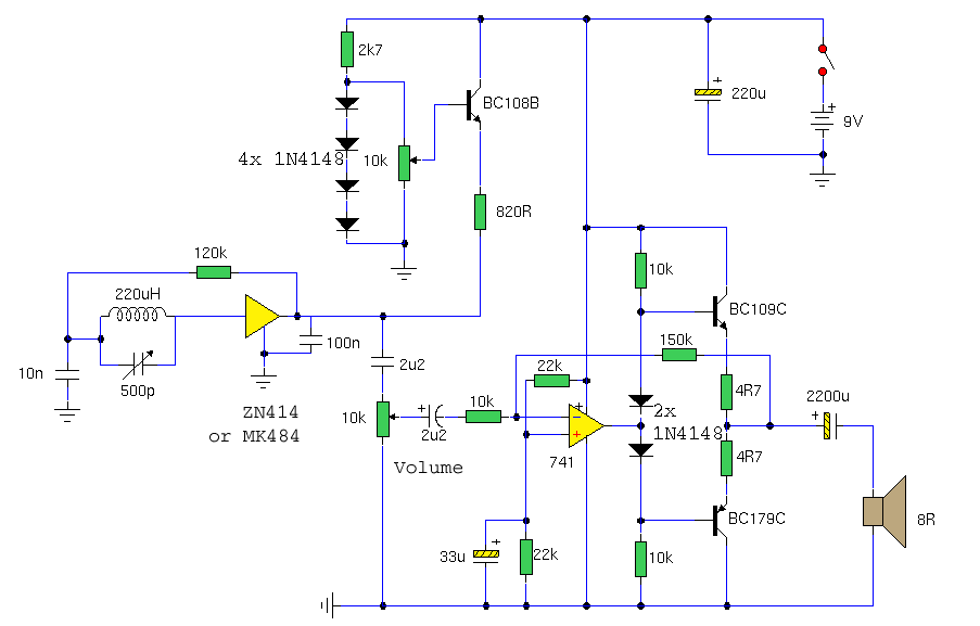
ZN414 Portable Receiver
Circuit : Andy Collinson
Email: anc@mitedu.freeserve.co.uk
Description:
An AM portable radio receiver made from the ZN414 IC. The ZN414 ic has now been replaced by the MK484
which is identical in performance and pinout.
Notes:
Designed around the popular ZN414 IC this receiver covers the medium wave band band from approximately 550 to 1600 KHz
with the values shown. The coil and tuning capacitor may be taken from an old MW radio to save time.
The ZN414 IC, has now been replaced by the MK484. The integrated circuit is a 3 pin, tuned radio frequency circuit, and
incorporates several RF stages, automatic gain control and an AM detector. It is easily overloaded and the operating voltage of th
IC is somewhat critical to achieve good results.
In this circuit a small voltage regulator is built around the BC108B transistor, four 1N4148 diodes, the 2k7 and 10k preset resistor
and the 820R resistor. The 10k pot acts as a selectivity control for the whole receiver, controlling the operating voltage for
the ZN414 (or MK484). If you live in an area that is permeated with strong radio signals, then the voltage may need to be decreased.
I found optimum performance with a supply of around 1.2 volts.
The audio amplifier is built about an inverting 741 op-amp amplifying circuit. Extra current boost is provided using the BC109C
/ BC179 complementary transistor pair to drive an 8 ohm loudspeaker. The voltage gain of the complete audio amplifier is around 15.
The audio output of the complete receiver is really quite good and free from distortion. I may provide a sound sample later. Click
here to see a picture of my prototype. I used a small wooden enclosure and the complete
tuning assembly from an old radio.

