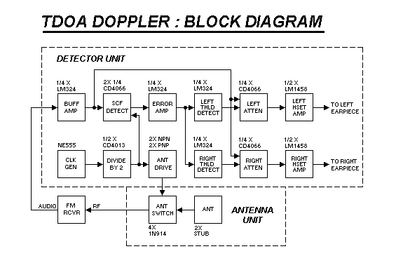

From here, the error voltage is fed to a pair of op-amps, connected to serve as
voltage comparators, ( "threshold detectors" in the block diagram ) and the
outputs of these comparators are used to open / close CMOS switches that
enable / disable two separate ( 20 db ) audio attenuators... one in each earphone
audio channel. The two audio channels are then amplified with op-amps and
buffered with discrete transistors to provide a drive level suitable for 8 - ohm
stereo headphones.
A 555 oscillator serves as a 1000 Hz clock source, which drives a D - type flip flop ( divide by 2 ) to achieve a fully - symmetric 500 Hz switching clock, with two complementary outputs. These two outputs are used to drive the SCF / detector, and are also buffered with discrete transistors to provide drive signals for the antenna switching diodes.
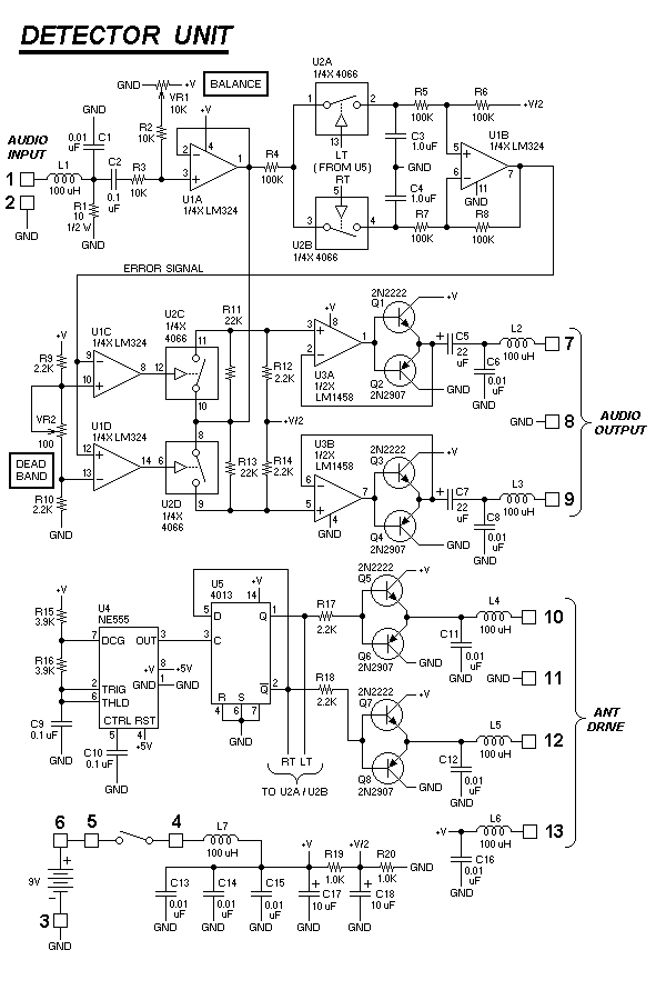
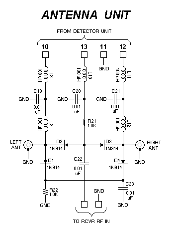
The figures below show the schematics of the unit. Note that all inputs and outputs of the detector board are filtered with small RF chokes, and RF bypass capacitors. Much greater attention was paid to EMI / RFI "hygiene" in this unit, ( compared to the mobile unit ) because there is a far greater chance that this unit will be used in a "high radiation" environment... directly adjacent to a transmitting antenna. For identical reasons, the PC artwork employ "boundary etching" methods, to maximize the area of the ground plane, and reduce sensitivity to RFI.

The PC board for the detector fits into a SerPac enclosure model A-27-9V, which
has a compartment for a 9 volt battery, and a small panel suitable for mounting
the various jacks and connectors. It is small enough to be easily carried on the
belt of a hunter. This enclosure is plastic, and ( therefore ) offers no EMI
shielding, but various "tricks" can be employed to achieve this, ( described in the
next section ) or some other type of enclosure can be used.
CMOS circuits were employed for battery conservation, and to eliminate the need for a voltage regulator. Each CMOS switch is "closed" when its control input equals +9V, and "open" when control = GND. The audio attenuation is set by the values of R11 / R12 ( for one channel ) and R13 / R14, for the other channel.
The audio output amplifiers use complementary transistors to provide enough drive capacity for 8 ohm headphones. Note that the feedback signal for these ( unity gain ) amplifiers is taken from the transistor emitters, rather than from the output of the op-amp... this eliminates the non - linear behavior of the base - emitter junctions, so no loss of audio fidelity will occur. It also means that the transistors used are not really important... they do not have to be a "symmetric pair" of transistors... any NPN / PNP "pair" should work equally well.

The PC board for the antenna switching unit is much smaller, and designed for
mounting in a SerPac enclosure, model C-4. Again, this enclosure is plastic and
offers no RF shielding, but some "tricks" can be used to achieve this, ( e-mail me )
or another type of enclosure can be used. The prototype unit did not appear to
suffer any adverse effects due to this lack of shielding.
In any event, the ANTENNA unit should be mounted directly on the headset... I used tie wraps to secure mine to the top/center of the headband, equidistant from each antenna. The co-ax cables to each antenna should be of equal length, within one inch.