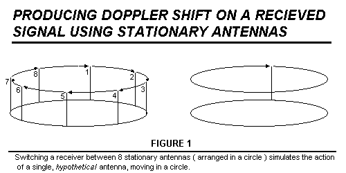

To generate a significant amount of Doppler shift, ( about 500 Hertz at 144 MHz ) the antennas must be switched very fast... about 7.5 KHz in this D/F. With eight antennas, sequentially switched at 7.5 KHz, the rotation rate of the hypothetical antenna is 7500 / 8 = (approx.) 470 Hz. If the antennas are arranged in a circle with a two foot diameter, this simulates the movement of a single antenna which is circling at a ( tangential ) speed of 3000 feet per second.... nearly three times the speed of sound. The antenna switching is achieved with diodes, to deal with the high switching rates.
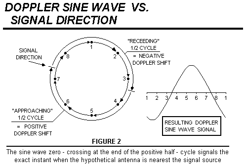
Audio filtering is required to remove any voice modulation, and to construct a Doppler sine wave with enough waveform quality to be useful. The filtered Doppler sine wave has two zero-crossing "events", which occur when the hypothetical antenna is "nearest to" the signal source, and "farthest from" the signal source. ( Figure 2 ) The "nearest to" zero crossing always occurs at the end of the positive half cycle, ( "falling edge" zero - crossing ) and it can be detected and used to signal the exact instant when the hypothetical antenna is closest to the transmitter signal.

The position of the hypothetical antenna can be tracked at every instant with a digital counter, which serves as the signal bearing counter. To guarantee "agreement" between the location of the hypothetical antenna, and the number in the bearing counter, the same counter is used to switch the eight ( stationary ) antennas, and to track the signal bearing.
When a falling - edge zero crossing is detected, a trigger pulse is generated and used to trigger a data "latch" which takes a "snapshot" of the binary number in the bearing counter, at that exact instant. The resulting "snapshot" data is used to drive a display, consisting of a circle of LEDís which show the relative bearing to the signal source.
Doppler modulation is a form of frequency modulation, ( FM ) caused by relative motion between the transmitter and receiver. Because it is a form of frequency modulation, an FM receiver is required to detect it. The Doppler modulation in this unit consists of an audio frequency sine wave, so it will pass through the audio amplifiers of an FM receiver with very little trouble, and can be "sampled" ( by the D/F display unit ) directly at the external speaker jack of the radio.... no internal modifications of the radio are required.
FILTERING THE DOPPLER SINE WAVE
This D/F employs a switched capacitor filter, ( SCF ) followed by two active, low pass filters, ( each with 2 poles ) to produce a Doppler sine wave with good waveform quality. The output of the zero-crossing detector triggers an adjustable 1-shot, which allows the D/F to be calibrated to eliminate any residual bearing errors. The switched capacitor filter is very simple, but it has some very interesting qualities which make it ideal for this situation... it behaves like a resonant bandpass filter, and ( unlike most filters ) requires an external clock, to operate it. ( The SCF clock determines the center frequency of the filter. )
In this D/F, the same clock which drives the antenna also drives the SCF, so
the center frequency of the SCF is always guaranteed to exactly equal the
frequency of the Doppler pulses. This allows the filter to be designed with a
bandwidth of only a few Hertz, resulting in excellent voice audio rejection.