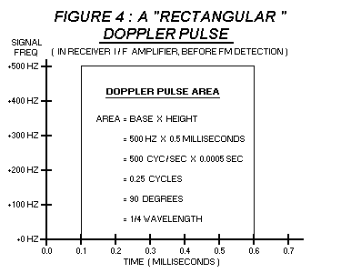
The figure below shows a "rectangular" Doppler pulse, with a deviation amplitude of +500 Hertz, ( in the I/F amplifier, before FM detection ) and a duration of 0.5 milliSeconds. It is possible to calculate the area enclosed in this pulse by multiplying its base ( 0.5 milliSeconds ) by its height. ( 500 Hertz = 500 cycles / second ). This area will be expressed in units of phase shift because cyc/sec x sec = cyc. Note that one cycle = 360 degrees = 1 wavelength.

DOPPLER PULSE INTEGRATION
By multiplying the Doppler pulse area by the detector coefficient, it is possible to discover how the pulse area will be "expressed", ( what units of measure ) after it is FM - detected. Because the "pre - detection" pulse area is expressed in units of hertz - seconds, and the detector coefficient is expressed in volts / hertz, the "post - detection" pulse area will be expressed in units of ( volts ) x ( seconds), or "volt - seconds". Therefore, it is necessary to feed this ( FM - detected ) signal into a circuit which will translate a signal from "volt - seconds" into volts. If this is done, the resulting voltage will be porportional to the cosine of the signal angle.
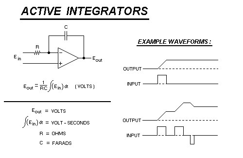
An integrator circuit is suitable for this task. An integrator circuit produces an output voltage which is porportional to the "area" of an input pulse. The term "integration" actually comes from a branch of mathematics called calculus.... It is the name of the procedure that is used to calculate the area underneath a mathematical "curve", plotted on a graph. In electronics, the term "waveform" can be substituted for "curve", so circuits which perform this function are called integrators.
In this D/F, the integration is actually performed by the Switched Capacitor Filter. A close examination of the SCF circuit will reveal that ( in one sense ) it is actually a set of eight RC - type integrator circuits, ( one for each antenna ) which are sequentially selected so that each antenna drives one specific integrator. ( the CD4051 chip is merely a rotary CMOS "switch", with a single pole and 8 switch "positions" )
Just as an FM detector can be characterized with a single specification called the detector co-efficient, so too can an integrator be characterized with a specification called the integration co-efficient. For an integrator, the input signal is expressed in units of volt - seconds, and the output is expressed in volts, so the co-efficient of an integrator would be expressed as volts per volt - second, ( output / input ) or by cancelling the common units, expressed simply as "1/seconds".
Multiplying the ( post - detection ) Doppler pulse area by the integration coefficient will yield the resulting (integrator) output voltage. This voltage (in turn) is porportional to the cosine of the signal direction, as observed by the antenna pair.
ACTIVE INTEGRATORS
An IDEAL integrator ( the MATHEMATICAL definition of an integrator ) is another matter... like elephants, an ideal integrator will never "forget" an input pulse... if a single pulse is applied to the input of an ideal integrator, it will drive the integratorís output voltage to some non-zero value, ( proportional to the pulse area ) which will remain there INDEFINITELY.... ( assuming no other pulses or signals are applied ) Furthermore, the maximum output voltage of an ideal integrator is not limited to the peak voltage of the applied waveform. ( another drawback of RC integrators )

ACTIVE SCFíS
Together, these facts imply that the bearing information from any particular ( single ) antenna rotation can be retained and used for a much greater time interval than would be possible from a simple RC integrator SCF. It should therefore be possible to use an antenna array with a greatly reduced radius... possibly even small enough to fit easily onto a PC board. It also impies that Dopplers could be constructed for operation on much lower frequencies... well down into the HF bands, or even lower...
With an active SCF, each antenna rotation adds directly to the total signal of all previous rotations... the signal from the 500th rotation would be just as effective as the signal from the first rotation... In geometric terms, this means that each successive rotation ( electrically ) increases the antenna radius by an amount equal to the actual ( physical ) radius of the array... 100 rotations of an array with a 6 inch diameter would yield as much output signal as one single rotation from an array with a diameter of 600 inches. ( 50 feet )
Any SCF that employs active integrators would require two CMOS switches... one for switching the input signals and one for switching the outputs. Furthermore, some means of deliberately "bleeding" the integrators would be necessary... otherwise, they would endlessly "pump up" until their outputs reached the limits of supply voltage for the op - amps.
Hmmmm..... very interesting.... maybe itís time for another PC board.....
[HOME PAGE]