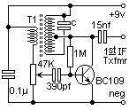


The circuit is basically an oscillator that does not quite oscillate, so when it is connectd to the IF HOT end of the first IF transformer it will increase the Q-factor, thereby reducing the IF bandwidth considerably. It does this by cancelling the losses in the 1st IF transformer using gain from an additional transistor circuit.
In the circuit given, T1 is a first IF transformer, from another one of these cheap radio's. The capacitor "c" is built into the IF transformer. Couple the output of this circuit to the 1 st IF transformer of the radio to be modified and peak the first 1 st IF for maximum received signal. Peak the transformer in the Q-multiplier circuit for maximum received signal then increase the 47K until oscillation just begins (you will hear a STRONG beat note). Re-adjust the transformer of the Q-multiplier for "Zero-Beat" (lowest frequency tone). Turn the 47K pot back until the tone just stops. That's it!!
Don't forget to turn the 47K pot to "zero" BEFORE you start tuning. You will now be able to hear the difference when you tune through SSB stations. The RX bandwidth is much narower, and reduces the adjacent channel signals to a more acceptable level. AM stations around 7.2MHz will now sound a bit muffled due to the reduced bandwidth.
This circuit will work well with almost ANY radio having an IF of 455KHz, but for God's sake DO NOT TRY IT ON A VALVE RECEIVER!! The high voltages could be lethal.
Have fun, de HARRY, Lunda, Sweden. (GENTLY) hit "BACK" to return to my homepage