CW RECEIVER
FOR 80 AND 40 METERS
Cost estimate: $20-$30
This amazingly sensitive and dependable "Simplest Ham Receiver" is capable of receiving CW (Morse Code) signals.
It is crystal controlled and thus very stable and immune to drift and hand-capacitance detuning.
With my version of this receiver I have QSO'd 7 states with QRP power and monitored CW stations coast-to-coast using a dipole antenna just 12 feet off the ground.
Even without the oscillator section this radio receives amplitude-modulated shortwave broadcasts worldwide! Construction is straightforward and parts layout is not critical.
It's a great first construction project - no soldering is necessary.
Of course, a completely soldered version can be built if desired.
As knowledge and construction skill increases it can be improved and refined with add-on circuitry such as an Audio Q-Multiplier for enhanced performance and a VFO for tuning freedom.
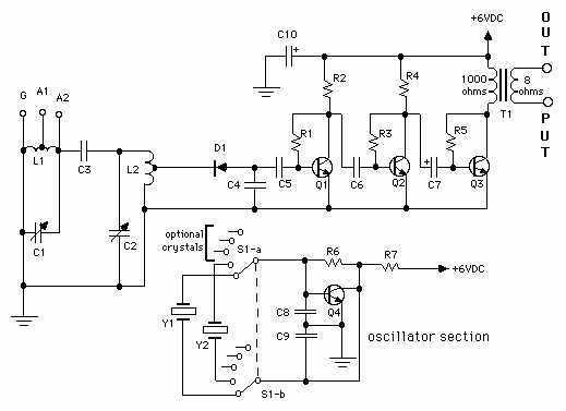
How it works: This is an old-fashioned amplified "crystal set" with a twist.
L1/C1 serves as an antenna tuner.
Amplitude-modulated shortwave stations are tuned in with L2/C2, converted to pulsating dc ("detected") by D1, filtered via bypass capacitor C4 and converted to ac by coupling capacitor C5.
The audio ac signal is then amplified with a three-stage transistor amplifier and monitored with headphones.
The tuning range is about 2-9 Mhz.
However, CW signals cannot be detected with this process, so an additional crystal oscillator section generates a frequency which is mixed with incoming CW by D1, yielding both signal/oscillator-sum and signal/oscillator-difference signals.
The sum-signal is beyond the audio frequencies and therefore not usable, but the difference-signal of these is an audio frequency that is detected by D1, filtered, coupled, amplified and heard via common 8-ohm impedance headphones attached to the output end of T1.
Example: with a 3700KHz crystal installed, a 3700.500 kHz CW will have a pitch of 500Hz - and so will a 3699.500Khz signal.
Attention to the pitch of a given signal is needed because all audio frequencies on BOTH sides of the crystal frequency are heard.
The principle for receiving CW used here is the oldest still is use: direct conversion.
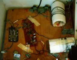
 Construction: Fahnstock clips can be used to connect all parts except for wires attached to C1, C2, L1, L2, S1 and the crystal holder: alligator-clip, twist, or wrap the wire leads to those components.
Using the schematic diagram as a guide, arrange the parts on a wooden board to determine the spacing of the clips according to leads of the components, then screw the clips to the board and attach parts point-to-point.
The two coils L1 & L2 are mounted at a 90-degree angle to avoid mutual interaction.
Keep the output well away from the antenna input as illustrated.
Construction: Fahnstock clips can be used to connect all parts except for wires attached to C1, C2, L1, L2, S1 and the crystal holder: alligator-clip, twist, or wrap the wire leads to those components.
Using the schematic diagram as a guide, arrange the parts on a wooden board to determine the spacing of the clips according to leads of the components, then screw the clips to the board and attach parts point-to-point.
The two coils L1 & L2 are mounted at a 90-degree angle to avoid mutual interaction.
Keep the output well away from the antenna input as illustrated.
The oscillator section is not wired to the rest of the circuit except for the power supply; it interacts by proximity only.
Octal Tube sockets can be used to hold crystals; each holds two.
Rotary switch S1 for switching crystals can be omitted and crystals can be switched by hand.
Alligator clips can be used as crystal holders - use what you have or can find!
An acceptable power supply is a single 6V lantern battery.
The 1000uF electrolytic capacitor C10 is connected at and between the terminals to avoid "motorboating." Be sure to observe polarity!
Adventurous builders can try substituting any of a variety of different audio amplifier circuits (such as an LM386 audio amp IC circuit) for the 3-transistor circuit depicted here.
The cost would be reduced and performance would be at least as good; such a circuit would include a volume control.
However, those that wish to avoid soldering should stick to the design described here because the leads of the transistors are nice and long!
Operation: Use the longest and highest antenna you can; 50 feet of wire thrown out the closest window and attached to a tree will do for starters.
If you don't have space for a long antenna, try an active antenna.
Connect the ground connection to a cold water pipe or metal stake driven a few feet into the earth.
After attaching the antenna to either A1 or A2 (whichever works best) and the ground at G, insert crystal(s).
Hook up battery and headset, then tune C2 until a CW station is heard.
Peak signal with C1.
Even if no stations are around when you are, a characteristic increased hissing will tell you when you are on frequency.
If you have a transmitter or oscillator of some kind such as a crystal tester you can use it with a close-to-frequency crystal to locate the signal.
If more signal is needed from the oscillator, clip a lead to the unused antenna post and drape it near the oscillator circuit.
NO DIRECT CONNECTION SHOULD BE MADE BETWEEN THE TWO CIRCUITS EXCEPT FOR THE COMMON POWER SUPPLY.
Note that you WILL hear shortwave amplitude-modulated (voice, music, etc) transmissions while tuning around with C2.
It's a nice bonus!
The receiver works for the 80- and 40-meter bands with the shown values.
With a few crystals spaced about 5 KHz apart for each band you're ready to monitor the CW airwaves on 80 and 40 meters;
if you have your "ticket" the crystals can of course be used in transmitters.
TIP: A TV colorburst crystal is perfect for monitoring the ARRL's WIAW East Coast station on 80 meters.
You can experiment with readjusting the coil windings to try receiving bands up to 20-meters, but avoid the 160-meter band: it's too close to the standard AM broadcast band and there is a (small) possibility of interfering with neighbors' reception.
PARTS LIST
Semiconductors
D1--------1N34A germanium diode or equivalent
Q1,Q2,Q3--SK3835 or ECG103A transistor, NPN, germanium, or any equivalent type
Q4--------Transistor, NPN, high-frequency, small-signal, silicon
          (almost any common type will work)
Capacitors
C1,C2---365-pF variable
C3------4.7-pF, 15-WVDC ceramic-disc
C4------0.001-uF, 15-WVDC ceramic-disc
C5,C6---0.1-uF, 15-WVDC ceramic-disc
C7 -----10-uF, 15-WVDC electrolytic, axial lead
C8,C9---100-pF, 15-WVDC ceramic-disc
C10-----1000-uF, 15-WVDC electrolytic
Resistors
R1,R3,R5,R6---470,000-ohm, 1/4-watt, 10%
R2,R4,R7---------4700-ohm, 1/4-watt, 10%
Additional Parts & Materials
Headset---- Common "Walkman" variety.
If using old-style high-impedance (1-3K) "cans,"
                 replace T1 with 1:1 interstage transformer.
L1,L2-------11 turns of #20-22 AWG enameled ("magnet") wire spaced 1-inch,
                 center-tapped, on 2-1/4 inch OD form (plastic
                 pipe, wood, etc...I used rolled-up light cardboard!)
S1----------2-pole, 6-position break-before-make, rotary switch
T1----------Transformer, 1000-ohm to 8-ohm, audio (Radio Shack, among others, has these)
Y1,Y2-------Crystals for 80- or 40-meter amateur bands
Pine Board--About 1x10x17 inches long, 28 Fahnstock Clips and #4 wood screws 1/2-in long,
                 brackets for mounting variable capacitors and switch (if used),
                 octal socket(s), hookup wire, knobs, etc.
..need parts?...
Improvements: An Audio Q-Multiplier dramatically improves selectivity and serves as a volume control.
Adding a VFO allows more tuning capability; the crystal oscillator can then be used for calibration.
Converters for other bands can be added to monitor those signals with this receiver.
Source:
Lisle, Larry, "The Simplest Ham Receiver"
                     (Hands-on-Electronics, Vol.5, No.6, June 1988, pp.63-65)
***HOME***
***Q-MULTIPLIER***
***2-BAND VFO***
***500mW TRANSMITTER***
***3W 2-BAND TRANSMITTER***
***15 METER CONVERTER***
***15 METER VXO-TUNED TRANSMITTER***
***FIELD STRENGTH METER***
***WATTMETER***
***CRYSTAL TESTER***
***SUPPLIERS***
comments?
email: jandg@brink.com