
Some months ago I began work on an all valve (tube) general coverage receiver for the HF bands. The prototype is now finished, but as I rebuild it on a decent chassis I will post any correction. This should only affect the coil.

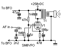
The AF valves chosen all have an anode current from 30 - 50 mA, and a Vg1 of about -6 volts. The cathode resistor must be therefore be (Ia + Ig2) / Vg1 or about 200 ohms for Ia = 30 mA. Make this resistor 470 ohms so the valve is run at about 10 - 15 mA. This will only 'tickle' it so the valve should last as long as you do. The 47K resistor supplying current to G2 is merely a token gesture to help the valve draw a few more milli-amperes and reduce distortion.
The valve anode impedance is about 4000 ohms. Matching 4000 to a 3 ohm speaker requires an impedance ratio of about 1333:1 or a turns ratio of 36:1. A 9 volt 10 watt mains transformer works nicely. Use a cheap transformer so that you can take away the laminations (expensive ones are laquered so it is damn near impossible to take them apart). The laminations are normally composed of 'E' and 'I' shaped plates, inserted alternately into the coil former. This is not good for our purposes as the anode circuit of the valve has a DC component that could cause the transformer to saturate. We need to reassemble the transformer laminations with all the 'E's inserted into the former from THE SAME SIDE withthe 'I's clamped across the open side. The 'I's must also have a thin sheet of typing paper between them and the 'E's.
When the transformer is connected to the power amplifier valve there will be a small amount of mains 'hum' heard in the speaker. Heavy smoothing capacitors cost money, so connect the transformer primary 0-volt terminal to the anode of the valve and connect the transformer 230-volt terminal to the +250vDC supply. The 220-volt tapping is used to take the +250 volts to the rest of the receiver. Any ripple from the PSU will be heard in the speaker, but any 'hum' coming from the rest of the receiver will be in anti-phase so it should cancel out.

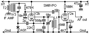
The BFO signal from V2b is also fed into the detector via a 2p capacitor. This capacitor can almost be formed by twisting two bits of single-strand insulated hook-up wire together. The cathode resistor of V2b has been increased to 22K so the current drawn by this valve is almost nothing. If it fails to oscillate then reduce the value a little. Here we do not need a BFO that is kicking out a watt or more of power, so 'birdies' and other unwanted RF signals inside the receiver can be minimised by running the BFO at the smallest current we can get away with.

All coils will be discussed at the end of this article, but I do reccomend the 455KHz valve IF transformers supplied by Vintage Electronic Supply Co. Tempe, USA.

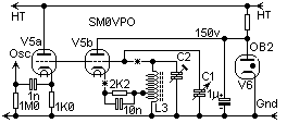
The sections of the tuned circuits are connected at the points marked with an '*' via the band switch. A 2-pole 6-way switch is required for the RF mixer stage. This switch should have two wafers, the second is required in the oscillator stage.
As you can see, there has been no provision for AGC but you may be able to add this yourself later. I saw AGC as an unnecesary luxury. I use a 1K ohm pot across the antenna and feed the receiver from the pot wiper. This forms an RF gain control. If I find the inclination I may add it to my receiver and post the modified circuit on this page.
Coils are listed at the end of this project.

In exactly the same way as the RF mixer stage, the sections of the tuned circuits are connected at the points marked with an '*' via the band switch. A 2-pole 6-way switch is required for the Local Oscillator stage.
The OA2 (or OB2) valve is a cold-cathode voltage regulator for 150 volts. I didn't use one because I am too stingy to spend the money (I am British so you have to make some allowances). I used six 24v Zener diodes in series. I have plugged them into a B7G (Miniature) valve base so that I can use a cold cathode tube as an alternative, if Zener diodes ever become obsolete.
The 2K2 resistor in the cathode of the oscillator valve is changed along with the coil for the band. This resistor should be selected for the highest value that allows the oscillator to reliably oscillate across the full band.
Coils for the oscillator are listed at the end of this project.

All the valve heaters are connected to 6.3 volts AC. See my article on getting 250vDC and 6.3vDC.
L1
205 turns on a 1/4" (6mm) former fitted with a ferrite slug. (updated*)
L2
(updated*) means that coils modified to suit final version of the receiver.
Check that the resistance between the +250 volt HT line and chassis (-ve) is over 500K ohms with the BLACK lead of the ohm-meter to the +250 volt HT line. The resistance may initially be under 1000 ohms until the capacitors have charged up to the voltage supplied by the meter.
If all is well you may now remove the ohm-meter (if you value it) and connect the power-supply.
AF AMPLIFIER
Touch V1 Grid-1 and V2a Grid terminals with your finger or the tip of a soldering iron. You should hear a loud buzz. Couple your walkman stereo to G1 and you will hear the music. If you don't then switch OFF, discharge the HT smoothing capacitors and check your wiring again.
IF AMPLIFIER & BFO
Place a 47K ohm resistor across the primary of T2 (last IF transformer). If you have the luxury of an RF signal generator then couple it to T3 with a temporary 20 turn winding. You should hear a lovely beat-note as you tune through 455 KHz. Adjust the BFO coil for the zero-beat at 455KHz. Tune T2 and T3 top and bottom ferrite slugs for maximum signal, with the BFO control set to about 1KHz either side of zero-beat. With the IF transformers from Antique Electronic Supply Co. I found the bandwith a little too narrow for SSB/AM so they may need to be "stagered" a little (tuned with signals 500Hz apart).
If the signal is VERY strong (over 200 mV) the BFO may be 'pulled'. This is what happens if a strong signal is fed INTO the BFO oscillator circuit. It is aparent by an unclear 'zero-beat'. When approaching zero-beat the oscillator suddenly snaps to zero-beat. In this case, reduce the 2p capacitor in value until the effect stops. If the 2p capacitor is too small you will just have a low AF output from the receiver.
After alignment of the IF amplifier is complete, increase the value of the 47K ohm resistor until the IF amplifier begins to self-oscillate, then reduce it to the nearest preffered value. In my case this was 220K ohms. If there is any tendency to become unstable in normal operation, then reduce the resistor by one more preffered value.
RF ALIGNMENT
Set the bandswitch to range 1 (A-0.55 MHz - B-1.65 MHz) or
Set the bandswitch to range 2 (A-1.50 MHz - B-4.20 MHz) or
Set the bandswitch to range 3 (A-4.00 MHz - B-11.0 MHz) or
Set the bandswitch to range 4 (A-10.0 MHz - B-25.0 MHz) or
Set the bandswitch to range 5 (A-20.0 MHz - B-32.0 MHz) or
Set the bandswitch to range 6 (A-13.5 MHz - B-15.0 MHz)* or
Repeat the above steps for each waveband. * band 6 is your own choice. On my set it is 13.5 MHz to 15.0 MHz because I like 20 meters.
Sensitivity is about as expected (1.5uV Minimum Discernable Signal MDS), but it does fall off a little above 20 MHz (4uV MDS in the 28 - 30 MHz band).
I am quite happy with my receiver. Performance is about comparable with the Heathkit RG1 I used to have in the late 60s, but that is what I was aimimg for. I hope that you have as much fun with this receiver as I had, my fun will now continue as I rebuild it on a decent chassis.